Multi-story substrate treating apparatus with flexible transport mechanisms

a technology of transport mechanism and substrate, applied in the direction of transporting and packaging, vacuum evaporation coating, coating, etc., can solve the problems of inability to transport substrates to and from other directions, inconvenient treatment of substrates, and inability to treat substrates at all,

Active Publication Date: 2009-06-04
SCREEN SEMICON SOLUTIONS CO LTD
View PDF119 Cites 25 Cited by
  • Summary
  • Abstract
  • Description
  • Claims
  • Application Information

AI Technical Summary

Benefits of technology

[0006]This invention has been made having regard to the state of the art noted above, and its object is to provide a substrate treating apparatus that can transport substrates flexibly between adjoining treating blocks.

Problems solved by technology

In the conventional apparatus, when the main transport mechanism of one of the treating blocks breaks down or otherwise becomes unable to transport substrates (abnormal state), it becomes altogether impossible to transport the substrates to and from other, adjoining, treating blocks.
Only a single route (transport path) is available for transporting the substrates between the treating blocks, and thus transporting is lacking in flexibility.
Consequently, there occurs an inconvenience that the substrates cannot be treated at all even though the main transport mechanisms of the other treating blocks are in a normal condition.

Method used


Image

  • Multi-story substrate treating apparatus with flexible transport mechanisms
  • Multi-story substrate treating apparatus with flexible transport mechanisms
  • Multi-story substrate treating apparatus with flexible transport mechanisms

Examples


first embodiment

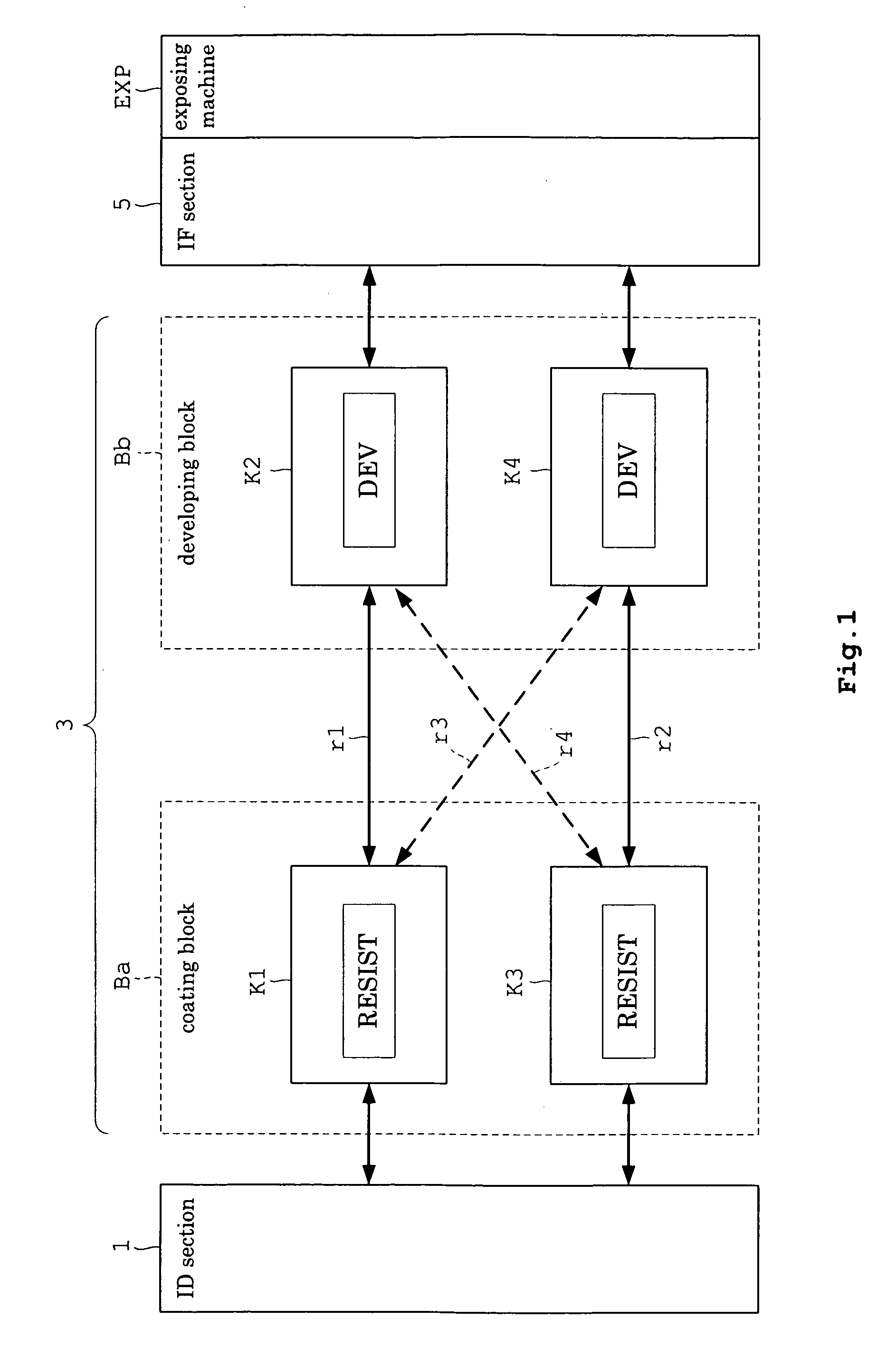
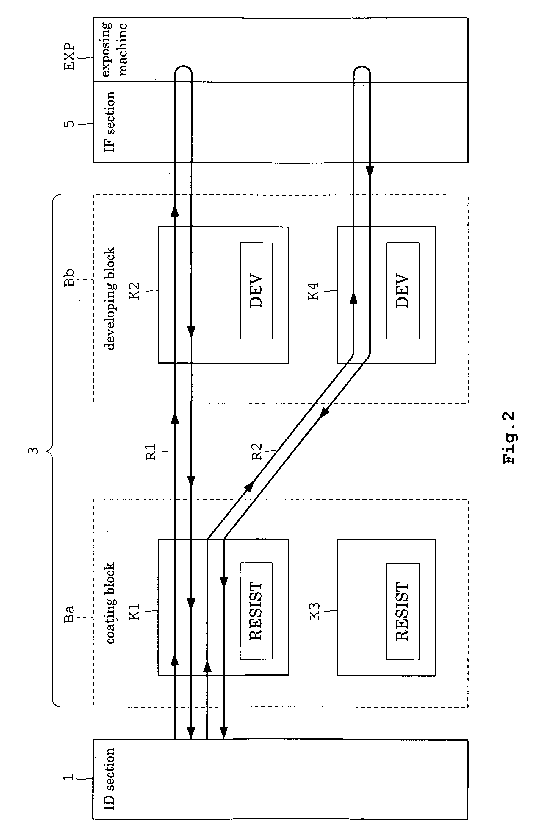
[0060]An outline of this embodiment will be described first. FIG. 1 is a schematic view showing an outline of a substrate treating apparatus in this embodiment.

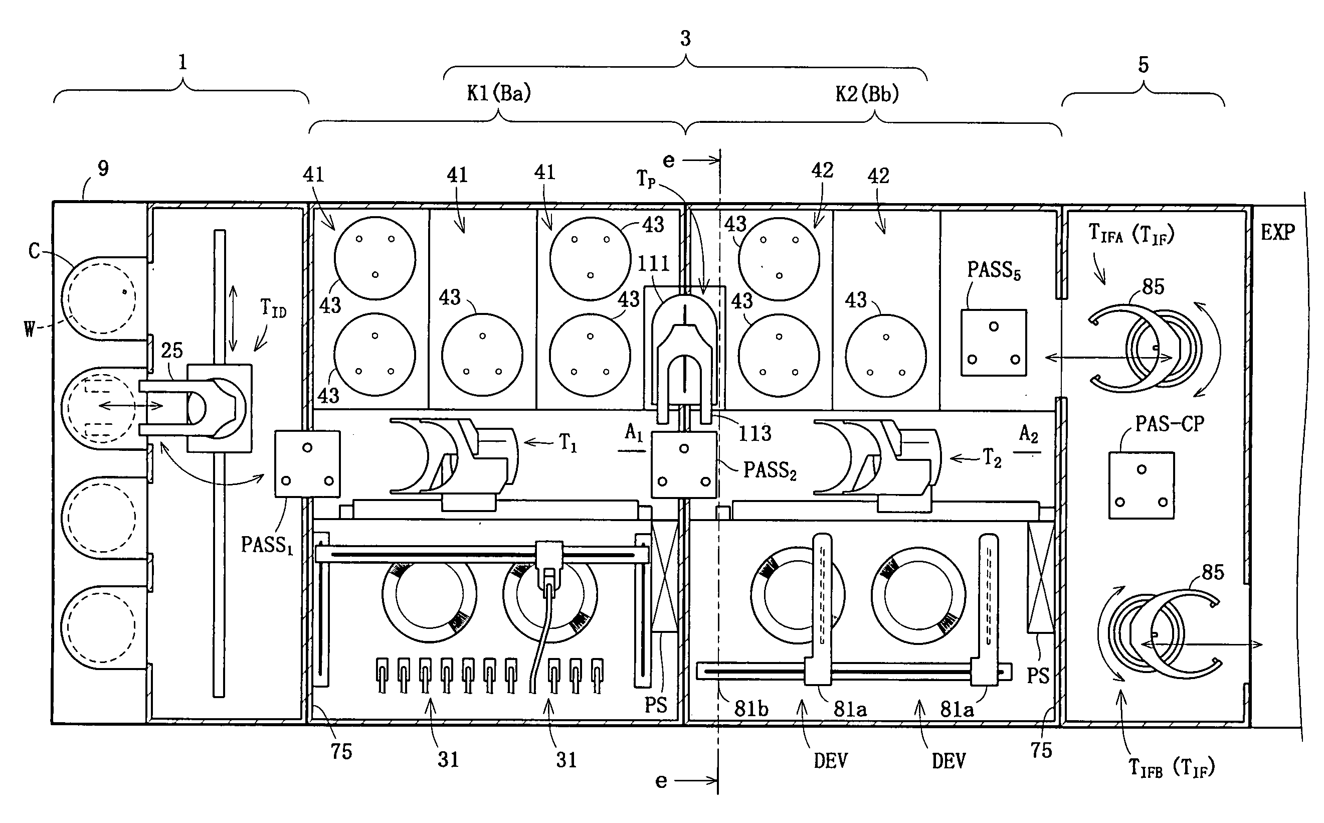
[0061]This embodiment provides a substrate treating apparatus for forming resist film on substrates (e.g. semiconductor wafers) W, and developing exposed wafers W. This apparatus includes an indexer section (hereinafter called “ID section” ) 1, a treating section 3, and an interface section (hereinafter called “IF section”) 5. The ID section 1, treating section 3 and IF section 5 are arranged adjacent one another in the stated order. An exposing machine EXP, which is an external apparatus separate from this apparatus, is disposed adjacent the IF section 5.

[0062]The ID section 1 receives wafers W transported to the apparatus from outside, and transports the wafers W to the treating section 3. The treating section 3 carries out treatment for forming film on the wafers W transported from the ID section 1, and treatment for devel...

second embodiment

[0176]The second embodiment of this invention will be described with reference to the drawings. In the second embodiment, the movable receiver MPASS is omitted from the substrate treating apparatus described in the first embodiment, and the construction of the main transport mechanisms T2 and T4 in the developing block Bb described in the first embodiment has been changed. Thus, the following description will be made centering on main transport mechanisms T2M and T4M of the second embodiment.

[0177]FIG. 17 is a view in vertical section of each transporting space in the substrate treating apparatus according to the second embodiment. As seen, there is no first blowout unit 61 or exhaust unit 62 between the transporting spaces A2 and A4 on the stories K2 and K4 of the developing block Bb. Therefore, the transporting space A2 and transporting space A4 are in communication.

[0178]Both the main transport mechanisms T2M and T4M are vertically movably supported by a common strut 101. The mai...


PUM

PropertyMeasurementUnit
flexibilityaaaaaaaaaa
heightaaaaaaaaaa
structureaaaaaaaaaa

Abstract

A treating section includes a plurality of treating blocks juxtaposed horizontally. Each treating block is vertically divided into stories. Each story includes treating units and a main transport mechanism. Substrates are transportable between the same stories of the treating blocks. Further, the substrates are transportable between different stories. Thus, the apparatus can transport the substrates flexibly between the treating blocks.

Description

CROSS-REFERENCES TO RELATED APPLICATIONS[0001]This application claims priority to Japanese Patent Application No. JP2007-310677, filed on Nov. 30, 2007, the entire disclosure of which is hereby incorporated by reference in its entirety for all purposes.BACKGROUND OF THE INVENTION[0002]This invention relates to a substrate treating apparatus for performing a series of treatments of substrates such as semiconductor wafers, glass substrates for liquid crystal displays, glass substrates for photomasks, and substrates for optical disks (hereinafter called simply “substrates”).[0003]Conventionally, this type of substrate treating apparatus is used to form a resist film on substrates and develop the substrates exposed in a separate exposing machine. The apparatus includes a treating section having, arranged therein, a coating block for forming film such as resist film, a developing block for developing the substrates, and so on. Each treating block includes a single main transport mechanis...

Claims


Application Information

Patent Timeline
Patent Type & Authority Applications(United States)
IPC IPC(8): B05C11/00
CPCH01L21/67173H01L21/67178H01L21/67745H01L21/67742H01L21/67276C23C14/568B05C13/02Y10S414/135H01L21/67703B05C9/12B05C11/08B05C13/00G03F7/16
Inventor OGURA, HIROYUKIMITSUHASHI, TSUYOSHIFUKUTOMI, YOSHITERUMORINISHI, KENYAKAWAMATSU, YASUONAGASHIMA, HIROMICHI
Owner SCREEN SEMICON SOLUTIONS CO LTD
Why Eureka
Try Eureka