
Multi-Position Valves for Fracturing and Sand Control and Associated Completion Methods

a technology of fracturing and sand control, which is applied in the direction of drinking water installation, borehole/well accessories, construction, etc., can solve the problems of increasing the risk of erosion, reducing the efficiency of fracking operations, and reducing the efficiency of sand removal

Active Publication Date: 2009-06-04
BAKER HUGHES INC
View PDF20 Cites 59 Cited by
  • Summary
  • Abstract
  • Description
  • Claims
  • Application Information

AI Technical Summary

Benefits of technology

[0006]A completion tubular is placed in position adjacent the zone or zones to be fractured and produced. It features preferably sliding sleeve valves one series of which can be put in the wide open position after run in for gravel packing and fracturing zones one at a time or in any desired order. These valves are then closed and another series of valves can be opened wide but with a screen material juxtaposed in the flow passage to selectively produce from one or more fractured zones. An annular path behind the gravel is provided by an offset screen to promote flow to the screened production port. The path can be a closed annulus that comes short of the production port or goes over it. For short runs an exterior screen or shroud is eliminated for a sliding sleeve with multiple screened ports that can be opened in tandem.

Problems solved by technology

There are many issues with this technique and foremost among them is the rig time for running in the hole and conducting the discrete operations.
Other issues relate to the erosive qualities of the gravel slurry during deposition of gravel in the gravel packing procedure.
Portions of the crossover tool could wear away during the fracking operation or the subsequent gravel packing operation, if the zone was particularly long.
The order of operations using this technique was generally limited to working the hole from the bottom up.
Alternatively, one trip multi-zone systems have been developed that require a large volume of proppant slurry through the crossover tool and that increases the erosion risk.

Method used


Image

  • Multi-Position Valves for Fracturing and Sand Control and Associated Completion  Methods
  • Multi-Position Valves for Fracturing and Sand Control and Associated Completion  Methods
  • Multi-Position Valves for Fracturing and Sand Control and Associated Completion  Methods

Examples


Embodiment Construction

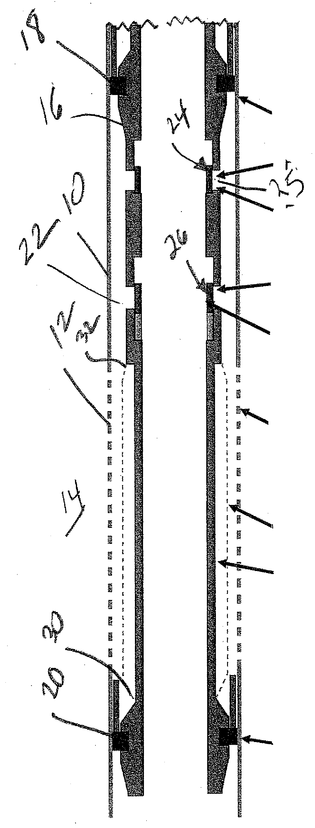
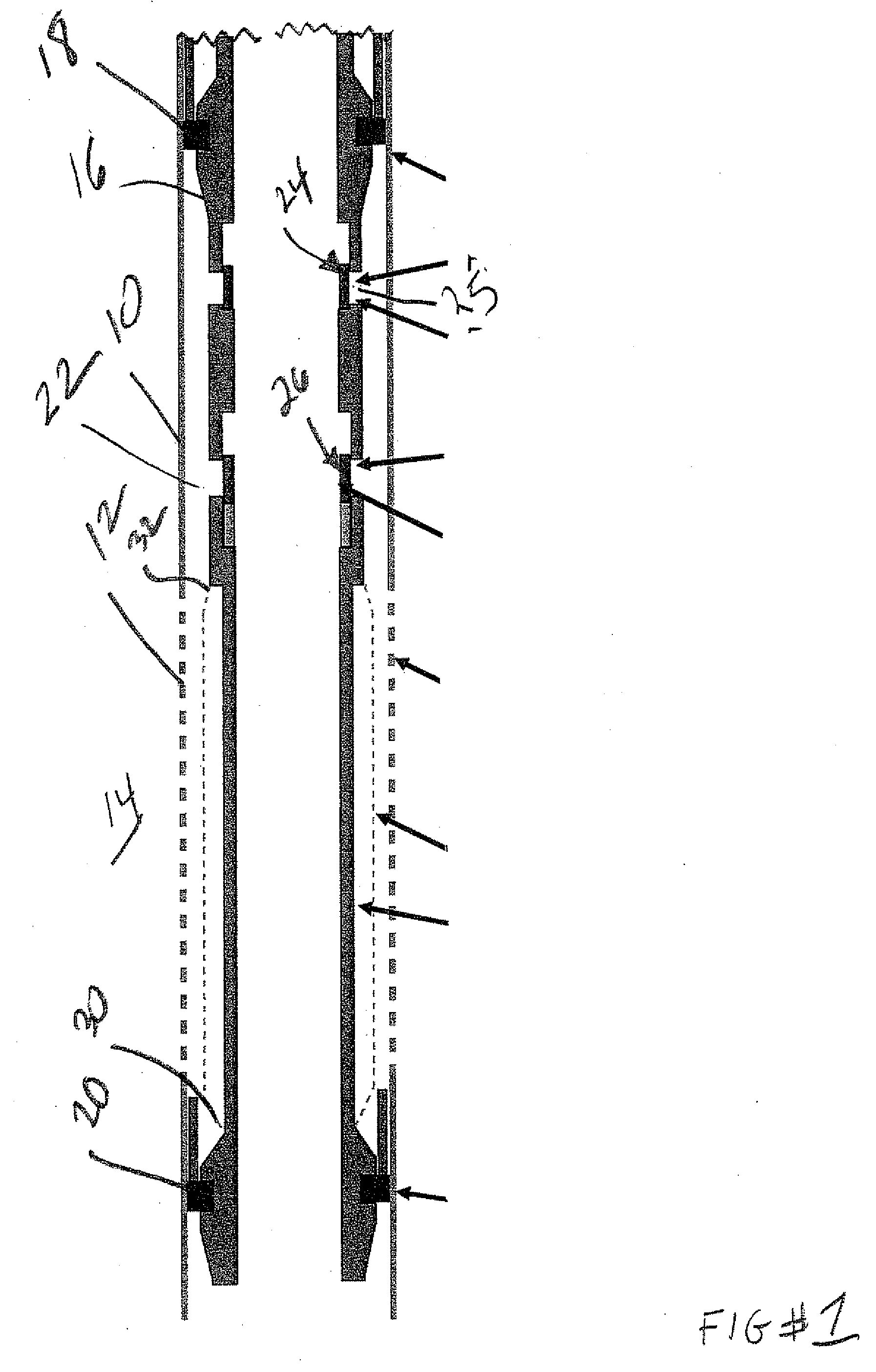
[0020]FIG. 1 is a schematic illustration of a wellbore 10 that can be cased or in open hole. There are perforations 12 into a formation 14. A string 16 is shown in part if FIG. 1 to the extent it spans a production interval defined between seals or packers 18 and 20. These seal locations can be polished bores in a cased hole or any type of packer. The two barriers 18 and 20 define a production interval 22. While only one interval is shown the string 16 can pass through multiple intervals that preferably have similar equipment so that access to them can occur in any desired order and access can be to one interval at a time or multiple intervals together.

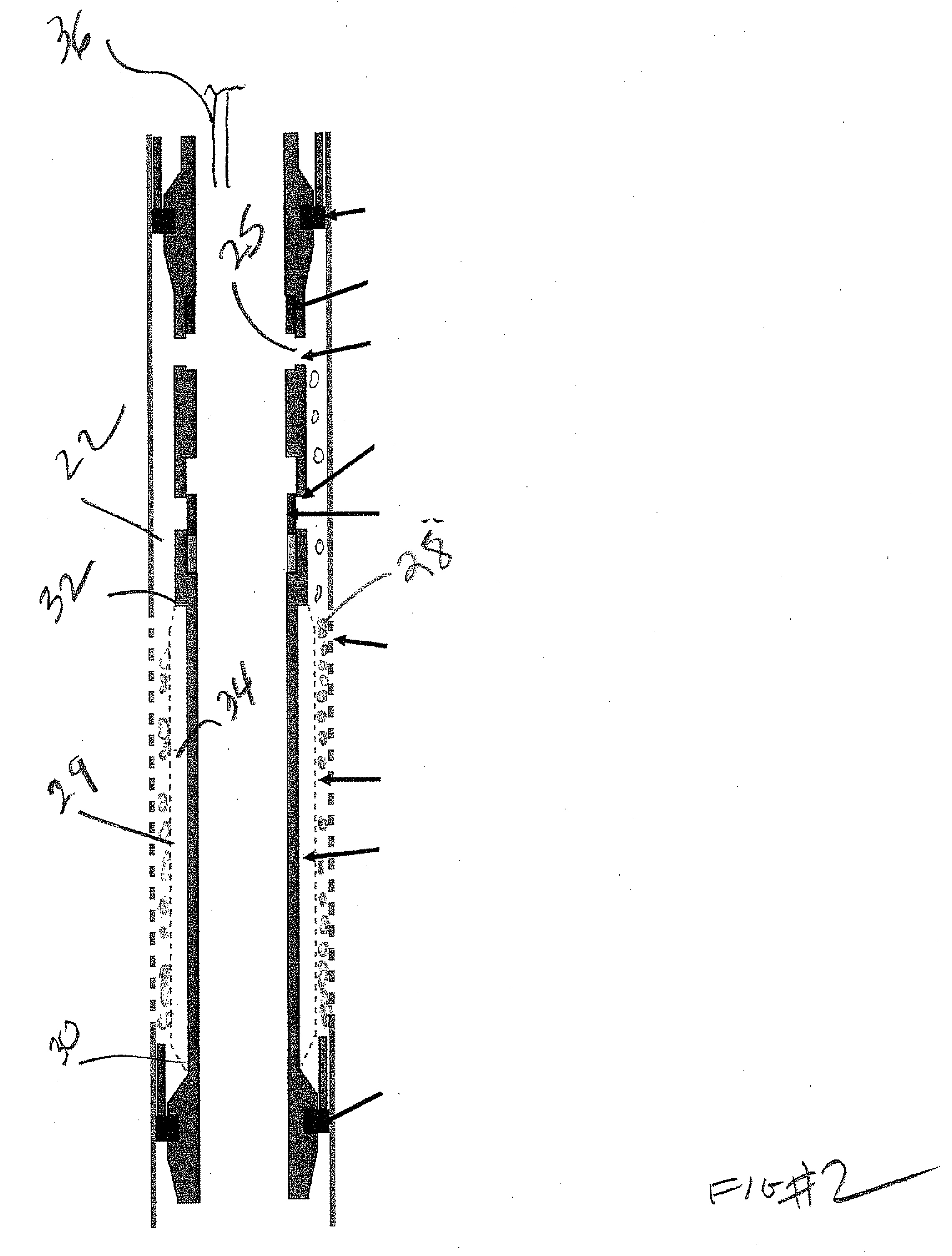
[0021]The string 16 for the interval 22 that is illustrated has a frac valve 24 that is preferably a sliding sleeve shown in the closed position in FIG. 1 for run in. Valve 24 regulates opening or openings 25 and is used in two positions. The closed position is shown in FIG. 1 and the wide open position is shown in FIG. 2. In the FIG....


PUM


Abstract

A completion tubular is placed in position adjacent the zone or zones to be fractured and produced. It features preferably sliding sleeve valves one series of which can be put in the wide open position after run in for gravel packing and fracturing zones one at a time or in any desired order. These valves are then closed and another series of valves can be opened wide but with a screen material juxtaposed in the flow passage to selectively produce from one or more fractured zones. An annular path behind the gravel is provided by an offset screen to promote flow to the screened production port. The path can be a closed annulus that comes short of the production port or goes over it. For short runs an exterior screen or shroud is eliminated for a sliding sleeve with multiple screened ports that can be opened in tandem.

Description

FIELD OF THE INVENTION[0001]The field of the invention relates to completion techniques involving fracturing and more particularly the ability to gravel pack and fracture discrete segments of a formation in a desired order through dedicated valved ports followed by configuring another valve for screened sand control duty to let production begin. A crossover tool and a separate run for sand control screens after the fracturing operation is not required.BACKGROUND OF THE INVENTION[0002]Typical completion sequences in the past involve running in an assembly of screens with a crossover tool and an isolation packer above the crossover tool. The crossover tool has a squeeze position where it eliminates a return path to allow fluid pumped down a work string and through the packer to cross over to the annulus outside the screen sections and into the formation through, for example, a cemented and perforated casing or in open hole. Alternatively, the casing could have telescoping members that...

Claims


Application Information

Patent Timeline
IPC IPC(8): E21B43/04
CPCE21B34/06E21B43/04E21B2034/007E21B43/14E21B43/261E21B43/08E21B2200/06
Inventor RICHARD, BENNETT M.JOHNSON, MICHAEL H.FAY, PETER J.
Owner BAKER HUGHES INC
Learn More