Relative inter-vehicle position calculation apparatus, transmission apparatus and program for same

a technology of relative inter-vehicle position and calculation apparatus, which is applied in the direction of instruments, measurement devices, beacon systems, etc., to achieve the effect of improving the accuracy of relative position calculation

Active Publication Date: 2009-06-04
DENSO CORP
View PDF2 Cites 18 Cited by
  • Summary
  • Abstract
  • Description
  • Claims
  • Application Information

AI Technical Summary

Benefits of technology

[0007]The method described above, that is, the calculation of the relative position of a vehicle based on the difference between the carrier wave phases from the first and the second vehicles, is designated as a Carrier-Phase DGPS positioning. Th

Problems solved by technology

However, a relative position calculation method that calculates the relative position based on the difference between two radio wave propagation times derived

Method used


Image

  • Relative inter-vehicle position calculation apparatus, transmission apparatus and program for same
  • Relative inter-vehicle position calculation apparatus, transmission apparatus and program for same
  • Relative inter-vehicle position calculation apparatus, transmission apparatus and program for same

Examples


first embodiment

[0017]Hereafter, the first embodiment of the present invention is described.

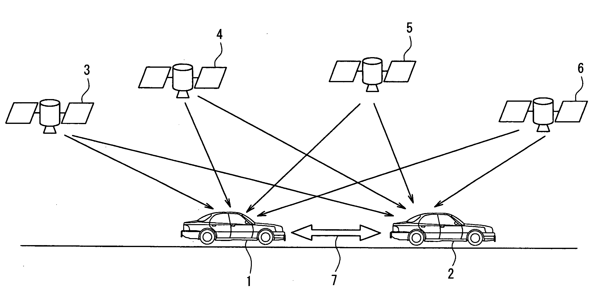
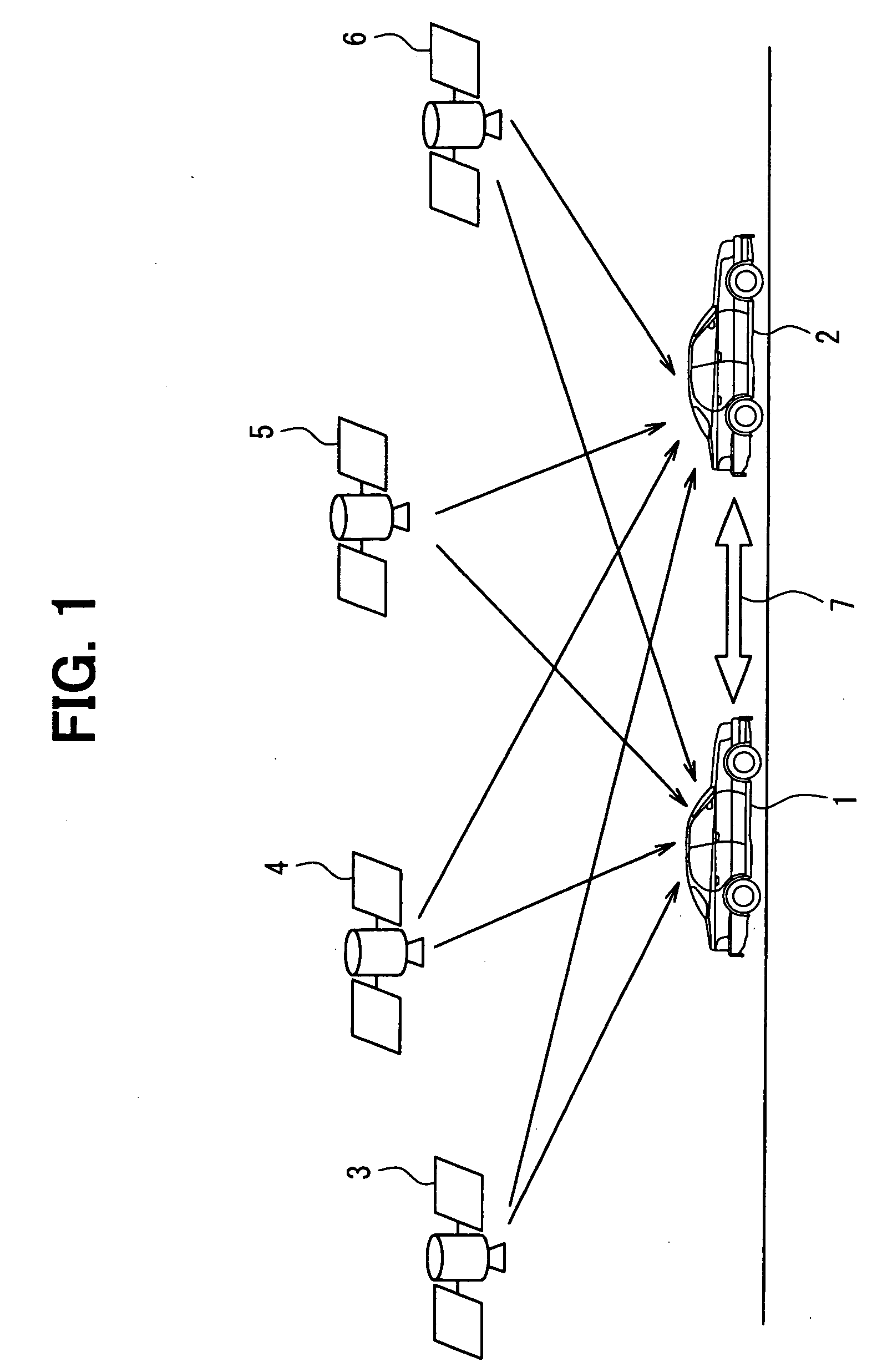
[0018]FIG. 1 shows the diagrammatic illustration of the telecommunication system according to the embodiment. In the present embodiment, vehicles 1 and 2 receive a radio wave (L1 band carrier wave) from two or more GPS satellites 3 to 6, and information on a carrier wave phase and the like of the received radio wave is exchanged mutually between the vehicles as indicated by an arrow 7. The difference between the carrier wave phase of the radio wave received by one of the vehicles and the carrier wave phase received by the other vehicle is then determined, and the relative position between the vehicles 1 and 2 is determined on the basis of the difference. In FIG. 1, the number of available GPS satellites for the vehicles 1 and 2 is 4, the number of the satellites may be only 3, or the number may be 5 or more depending on the situation.

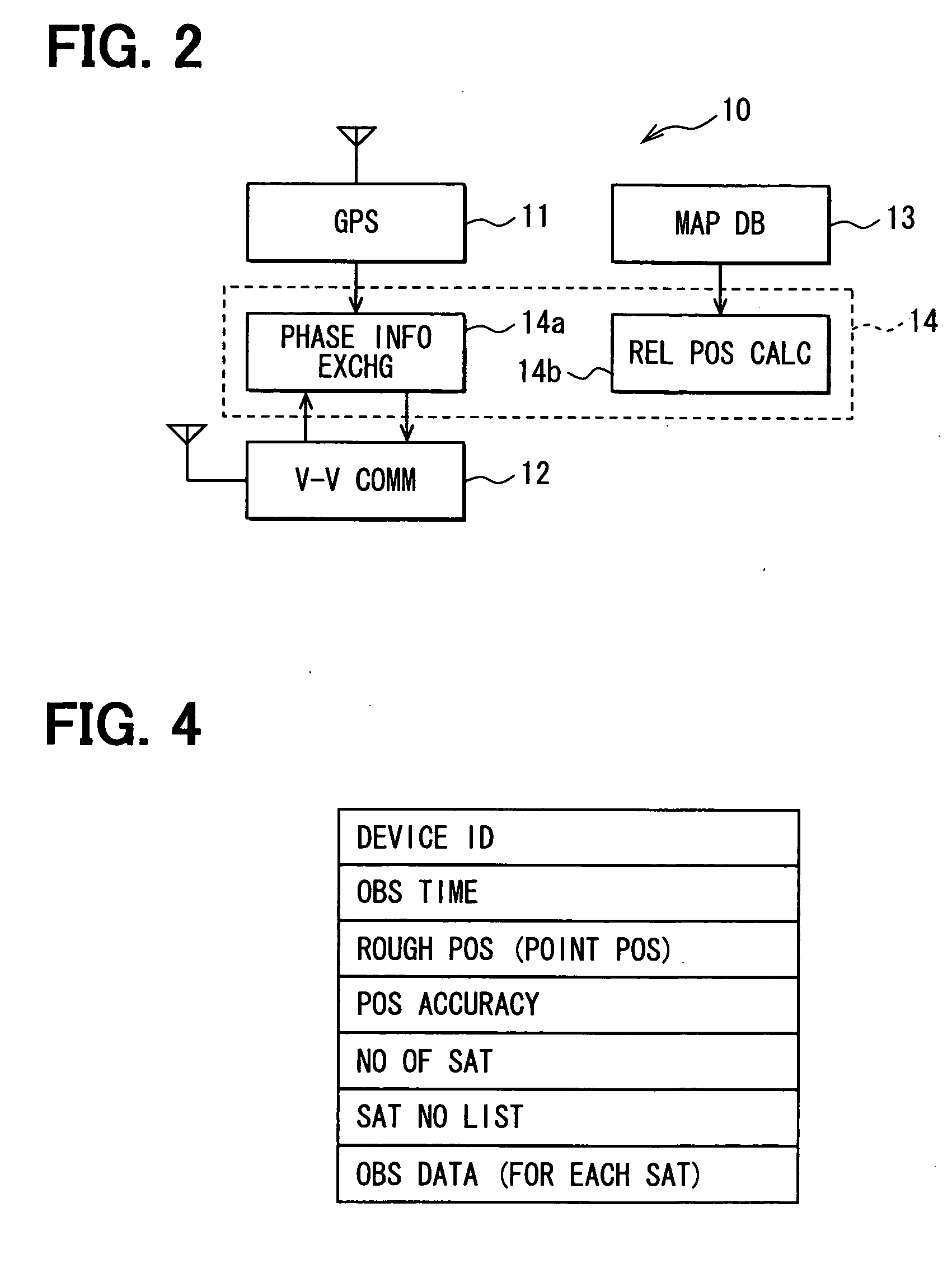
[0019]For realizing the function of the present invention, an on-board comm...

second embodiment

[0047]The second embodiment of the present invention is described in the following. The difference of the present embodiment from the first embodiment is that the control unit 14 of the on-board communication equipment 10 (Correspond to an example of the relative inter-vehicle position calculation apparatus) installed in the vehicle 1 repeatedly executes a program 200 shown in FIG. 7 in place of the program 100 of FIG. 3. The difference further includes the repeated execution of a program 300 in FIG. 8 by the control unit 14 in the on-board communication equipment 10 (Correspond to an example of a transmission apparatus) installed in the vehicle 2 in place of the execution of the program 100 of FIG. 3. According to the operation scheme described above, the on-board communication equipment 10 on the vehicle 2 only transmits information without receiving the information on the carrier wave phase and the like from the other vehicle, and the communication equipment 10 on the vehicle 1 o...


PUM


Abstract

An on-board communication equipment on each of two vehicles receives a radio wave from two or more GPS satellites, and determines a carrier wave phase of the received radio wave. Then, the on-board communication equipment on one vehicle receives, from the other vehicle, information on the carrier wave phase observed in the other vehicle. Further, the on-board communication equipment calculates a relative position of a self vehicle relative to the other vehicle by a Carrier-Phase DGPS positioning based on a difference between two carrier wave phases (e.g., single difference, double difference or the like), that is, one from the self vehicle and one from the other vehicle, both having the same observation time, from among the available carrier wave phases.

Description

CROSS REFERENCE TO RELATED APPLICATION[0001]The present application is based on and claims the benefit of priority of Japanese Patent Application No. 2007-313279 filed on Dec. 4, 2007, the disclosure of which is incorporated herein by reference.FIELD OF THE INVENTION[0002]The present disclosure generally relates to a calculation apparatus for calculation of relative inter-vehicle position, a transmission apparatus for transmitting information to the calculation apparatus, and a program for use in the calculation apparatus and the transmission apparatus.BACKGROUND INFORMATION[0003]A conventional technique for calculating a relative position between two vehicles based on a signal from navigation satellites is disclosed in a Japanese patent document JP-3,681,241 (also available as U.S. Pat. No. 5,999,880) for example. In the document, two vehicles respectively receive the signal from the GPS satellites for calculating signal transmission time (that is reversely proportional to a pseudo...

Claims


Application Information

Patent Timeline
IPC IPC(8): G01S1/00G01S19/48
CPCG01S19/43
Inventor SHAMOTO, MICHIO
Owner DENSO CORP
Why Eureka
Try Eureka