System and method for performing optical navigation using horizontally oriented imaging lens

a technology of optical navigation and imaging lens, applied in the direction of instruments, counting objects on conveyors, static indicating devices, etc., can solve the problems of reducing the tracking performance of the optical navigation system, affecting the system's stability, so as to improve the modulation transfer function and reduce the distortion of the system

Active Publication Date: 2009-06-04
PIXART IMAGING INC
View PDF4 Cites 6 Cited by
  • Summary
  • Abstract
  • Description
  • Claims
  • Application Information

AI Technical Summary

Benefits of technology

[0004]A system and method for performing optical navigation uses an imaging lens, which is positioned between a target surface and an image sensor array, that is orientated to be substantially horizontal with respect to the target surface such that the optical axis of the imaging lens is substantially perpendicular to the target surface. The orientation of the imaging lens enhances modulation transfer function (MTF) and reduces distortion for the system.

Problems solved by technology

For such orientation of the image sensor relative to the imaging lens, there are two significant drawbacks that will degrade the tracking performance of the optical navigation system.
The first drawback is that modulation transfer function (MTF) across the field of view will not be even due to the field tilt.
The second drawback is that distortion will be significantly high.

Method used


Image

  • System and method for performing optical navigation using horizontally oriented imaging lens
  • System and method for performing optical navigation using horizontally oriented imaging lens
  • System and method for performing optical navigation using horizontally oriented imaging lens

Examples


Embodiment Construction

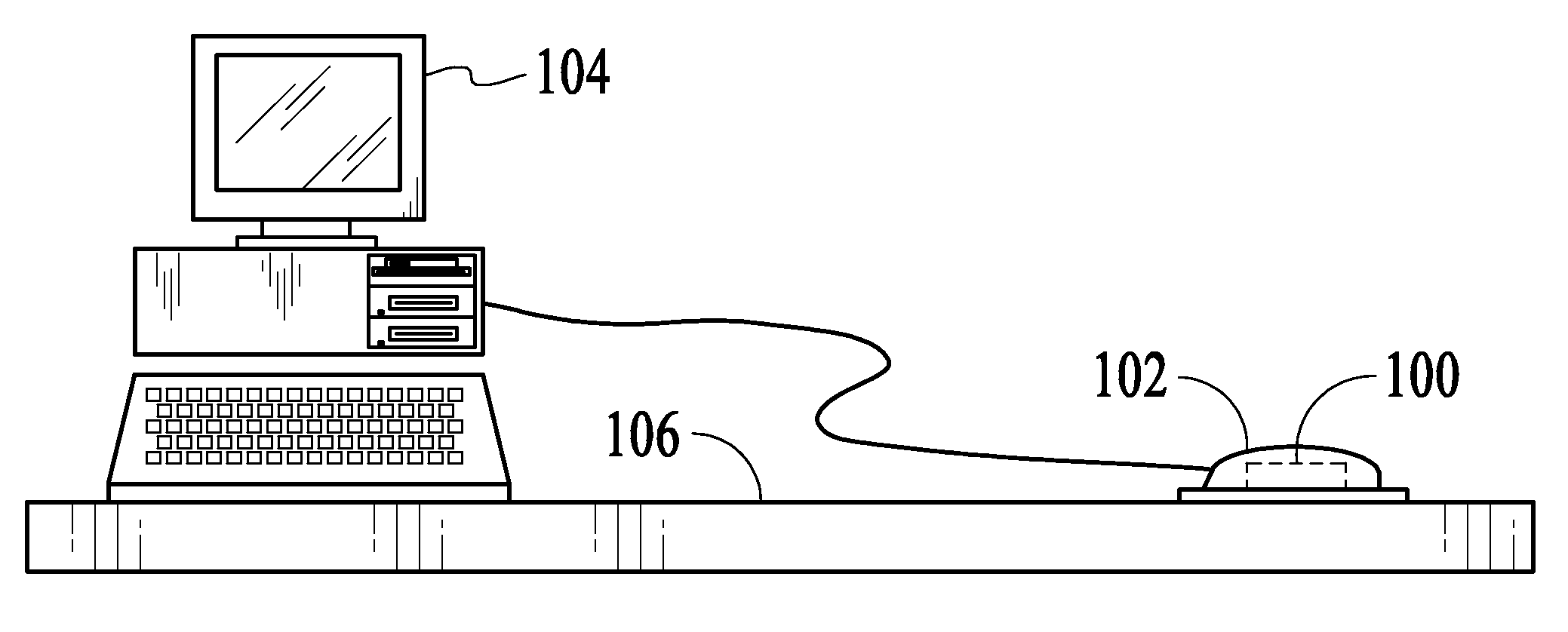
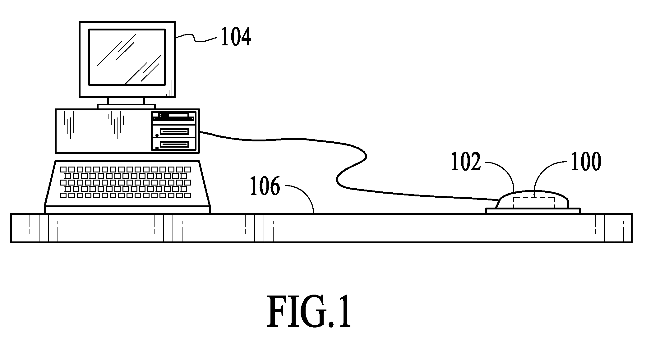
[0016]With reference to FIG. 1, an optical navigation system 100 in accordance with an embodiment of the invention is described. As shown in FIG. 1, the optical navigation system 100 is included in an optical computer mouse 102, which is connected to a computer 104. In other embodiments, the optical computer mouse 102 may be wirelessly connected to the computer 104. In this implementation, the optical navigation system 100 is used to optically track the movements of the optical mouse 102 as the optical mouse is manipulated over a navigation or target surface 106 by a user to control a cursor displayed on the computer 104. However, in other implementations, the optical navigation system 100 can be used in different products for various tracking applications. As described in detail below, the optical navigation system 100 is designed such that that the imaging performance of the system is enhanced with respect to modulation transfer function (MTF) and distortion. As a result, the over...


PUM


Abstract

A system and method for performing optical navigation uses an imaging lens, which is positioned between a target surface and an image sensor array, that is orientated to be substantially horizontal with respect to the target surface such that the optical axis of the imaging lens is substantially perpendicular to the target surface.

Description

BACKGROUND OF THE INVENTION[0001]Optical navigation systems detect relative movements between the optical navigation systems and navigation surfaces to perform tracking operations. An optical navigation system uses a light source, such as a light-emitting diode or a laser diode, with an illumination lens and an image sensor with an imaging lens to successively capture frames of image data of a navigation surface. The optical navigation system compares the successive frames of image data and estimates the relative movements between the optical navigation system and the navigation surface based on the comparison between the current frame of image data and a previous frame of image data. The optical navigation system is able to track the relative movements between the optical navigation system and the navigation surface by continuously capturing and comparing frames of image data. Optical navigation systems are commonly used in optical computer mice to track the lateral movements of th...

Claims


Application Information

Patent Timeline
Patent Type & Authority Applications(United States)
IPC IPC(8): G06F3/042G06K9/22
CPCG06F3/03543G06F3/0317
Inventor KRISHNAN, THINESHWARAN GOPALLEONG, YAT KHENGLEE, SAI MUN
Owner PIXART IMAGING INC
Why Eureka
Try Eureka