Static phase mask for high-order spectral phase control in a hybrid chirped pulse amplifier system

a phase control and high-order technology, applied in the field of laser light amplification, can solve the problems of mismatching dispersion properties, optical compressors cannot adequately compensate for the dispersion of optical stretchers, and no dispersion compensation techniques capable of compensating for dispersion matches above the fifth order in a hybrid cpa system

Inactive Publication Date: 2009-06-04
COHERENT INC
View PDF13 Cites 9 Cited by
  • Summary
  • Abstract
  • Description
  • Claims
  • Application Information

AI Technical Summary

Problems solved by technology

Mismatched dispersive element technologies in an optical stretcher and an optical compressor of a hybrid CPA system lead to mismatched dispersion properties.
Consequently, the optical compressor cannot adequately compensate for the dispersion of the optical stretcher in higher orders, such as fourth order, fifth order, sixth order, and above.
However, to date, no dispersion compensation techniques capable of compensating for dispersion matches abov

Method used


Image

  • Static phase mask for high-order spectral phase control in a hybrid chirped pulse amplifier system
  • Static phase mask for high-order spectral phase control in a hybrid chirped pulse amplifier system
  • Static phase mask for high-order spectral phase control in a hybrid chirped pulse amplifier system

Examples


Embodiment Construction

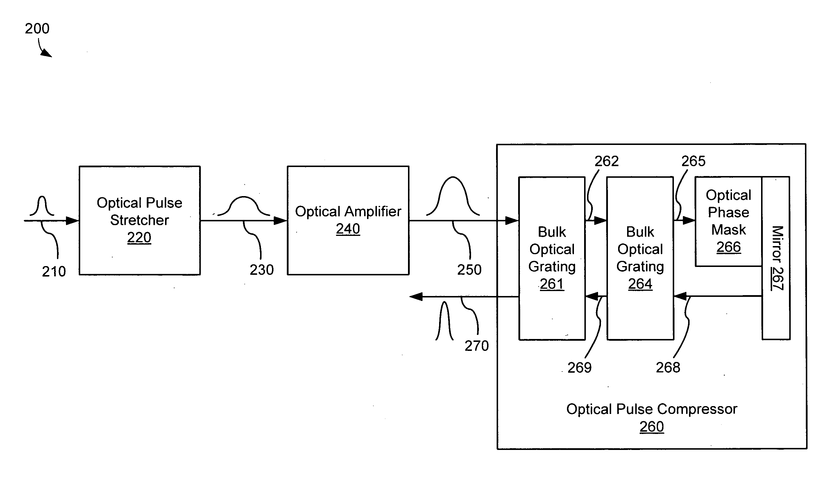
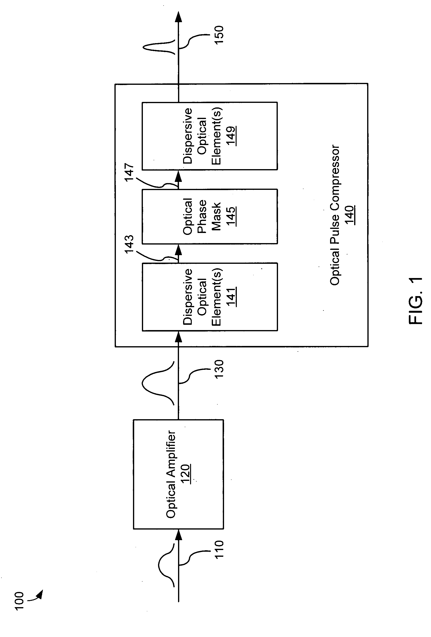
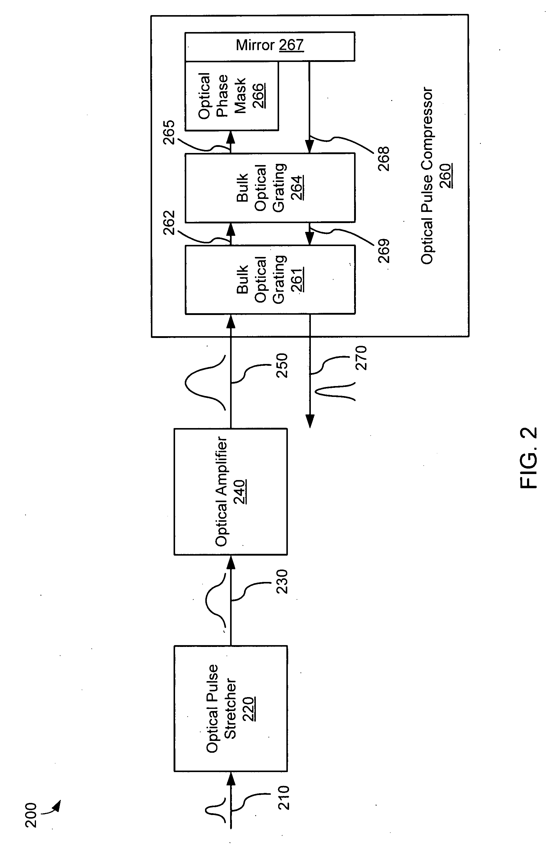
[0022]In various embodiments, a chirped pulse amplification (CPA) system comprises an optical pulse stretcher and an optical pulse compressor that are mismatched in that the optical pulse compressor includes a bulk optical grating while the optical pulse stretcher does not. Because the optical pulse stretcher and the optical pulse compressor are mismatched, higher order dispersion properties of the optical pulse stretcher and the optical pulse compressor are also mismatched and cannot effectively compensate for one another. High order dispersion compensation is provided by an optical phase mask disposed within the optical pulse compressor.

[0023]FIG. 1 is a block diagram illustrating a chirped pulse amplifier system 100, according to various embodiments of the invention. The chirped pulse amplifier system 100 comprises an optical amplifier 120 and an optical pulse compressor 140. The chirped pulse amplifier system 100 is configured to amplify and compress an input chirped optical pul...


PUM


Abstract

A chirped pulse amplification (CPA) system comprises an optical pulse stretcher and an optical pulse compressor that are mismatched in that the optical pulse compressor includes a bulk optical grating while the optical pulse stretcher does not. High order dispersion compensation is provided by an optical phase mask disposed within the optical pulse compressor.

Description

BACKGROUND[0001]1. Field of the Invention[0002]The present invention relates in general to the field of laser light amplification.[0003]2. Related Art[0004]Chirped Pulse Amplification (CPA) is very useful for producing ultrashort-duration high-intensity pulses for use in high peak power ultrashort pulse laser systems. CPA increases the energy of an ultrashort laser pulse while avoiding optical amplifier damage and excessive nonlinear distortion. In this technique, the duration of the pulse is increased by first dispersing the ultrashort laser pulse temporally as a function of wavelength (a process called “chirping”) to produce a chirped pulse, then amplifying the chirped pulse, and then recompressing the chirped pulse to significantly shorten its duration. Lengthening the pulse in time reduces the peak power of the pulse and, thus, allows energy to be added to the pulse without incurring excessive nonlinearities or reaching a damage threshold of the pulse amplifier and optical compo...

Claims


Application Information

Patent Timeline
IPC IPC(8): H01S3/00H04B10/12
CPCH01S3/0057H01S3/2308H01S3/10053H01S3/06754
Inventor GAUDIOSI, DAVID M.AKBULUT, MEHMETCAN
Owner COHERENT INC
Why Eureka
Try Eureka