Circuit board position structure

a position structure and circuit board technology, applied in the direction of casings/cabinets/drawers, electrical equipment, casings/cabinets/drawers details, etc., can solve the problems of time-consuming and complex, inconvenient practical operation, and complicated circuit layout of the motherboard, so as to improve the convenience of operation, quickly assemble and disassemble the circuit board, and stable installation

Inactive Publication Date: 2009-06-04
INVENTEC CORP
View PDF6 Cites 7 Cited by
  • Summary
  • Abstract
  • Description
  • Claims
  • Application Information

AI Technical Summary

Benefits of technology

[0012]The efficacy of the present invention lies in that, the positioning structure utilizes the matching effect of the base, the movable component, and the elastic element to make the movable component move along the joining direction together with the circuit board and the case to make the elastic element be elastically deformed. The stopper is used to being against the circuit board, so as to enable the circuit board to be stably installed on the case. The stopper is released from the circuit board to make the circuit board automatically move towards a releasing direction under the elastic restoring force of the elastic element, so as to make the circuit board be disassembled from the case. In this way, the user does not need to fix the circuit board through using a plurality of sets of bolts, so as to truly integrate the circuit board on the case through a screwless manner, such that the user can quickly assemble and disassemble the circuit board in a labor-saving way and the operating convenience is greatly improved.

Problems solved by technology

In the conventional manner of screwing and fixing the motherboard through using the copper bosses, during the process of assembling and disassembling the motherboard, the user must repeatedly screw and unscrew the bolts one by one, so it is quite time consuming and complex, which is quite inconvenient in the practical operations.
The current electronic devices are required to be light, thin, short, and small, too many copper bosses may occupy too much area on the motherboard, as a result, the circuit layout on the motherboard may become complicated, and the overall electronic device cannot be miniaturized.
However, the above manner of fixing the motherboard through using the thumb screw still belongs to a screwing manner, the process of assembling and disassembling the motherboard is quite complex, which is not only time-consuming, but the cost of the thumb screws is also higher than the conventional bolts, and as a result, both the material cost and the manpower cost are increased.

Method used


Image

  • Circuit board position structure
  • Circuit board position structure
  • Circuit board position structure

Examples


first embodiment

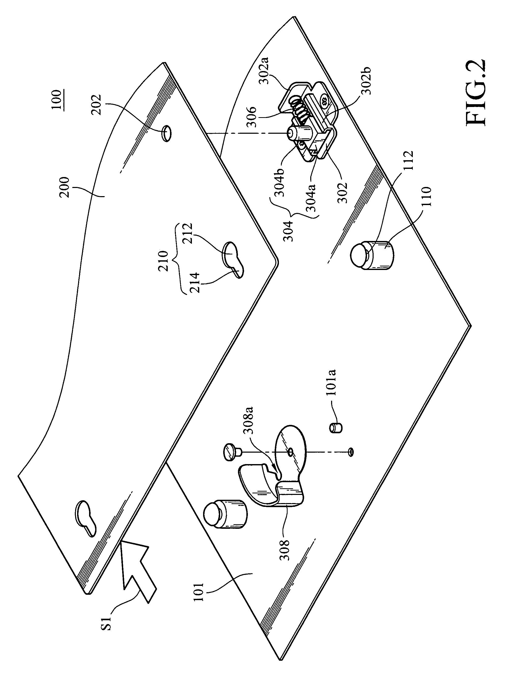
[0024]The elastic element 306 may be a compression spring or an extension spring. In the first embodiment, as shown in FIG. 2, the elastic element 306 is a compression spring. At this time, the elastic element 306 is disposed on a path of the joining direction for the circuit board 200 and the case 101. In other words, when the movable component 304 moves along the joining direction S1 of the circuit board 200, the sliding block 304a compresses the elastic element 306, such that the elastic element 306 is elastically deformed.

[0025]Alternatively, the L-shaped base 302 may be disposed to be horizontally rotated for 180° with respect to the L-shaped base 302 of FIG. 2, as shown in FIG. 2A. At this time, the elastic element 306 is an extension spring. That is, the elastic element 306 is disposed on the path of the releasing direction S2 for the circuit board 200 and the case 101. Therefore, when the movable component 304 moves along the joining direction S1, the sliding block 304 makes...

second embodiment

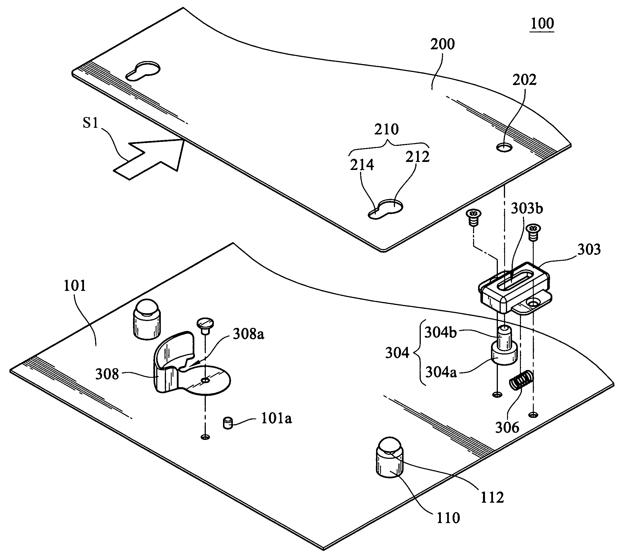
[0027]Referring to FIG. 3, it is a schematic three-dimensional exploded view of a positioning structure according to the present invention. Referring to FIG. 3A, it is a partial cross-sectional enlarged side view of FIG. 3. In this embodiment, the base 302 is, for example, the hollow housing 303. The hollow housing 303 has a chamber 303a and an opening 303b on the upper surface, and the aperture of the opening 303b is greater than the diameter of the pillar 304b of the movable component 304, such that the pillar 304b protrudes out of the opening 303b. The sliding block 304a of the movable component 304 is accommodated within the chamber 303a of the hollow housing 303, and the pillar 304b disposed on the sliding block 304a protrudes out of the opening 303b of the hollow housing 303 and passes through a through hole 202 of the circuit board 200. The elastic element 306 is disposed between the sliding block 304a and the hollow housing 303, and particularly, it is disposed between the s...


PUM


Abstract

A positioning structure is applied to an electrode device, which includes a movable component and an elastic element. The movable component is moved towards the joining direction for the circuit board and a case to press the elastic element, so as to deform the elastic element. A stopper is against the circuit board to fix the circuit board. Once the being against stopper is released from the circuit board, the elastic element pushes the circuit board along a releasing direction, and thereby the circuit board being conveniently disassembled.

Description

BACKGROUND OF THE INVENTION[0001]1. Field of the Invention[0002]The present invention relates to a positioning structure. More particularly, the present invention relates to a positioning structure of a circuit board.[0003]2. Related Art[0004]Recently, as the vigorous development of science and technology and information, computer equipment has become a quite popularized electronic device. As for the computer equipments available on the current market, no matter desktop computers, notebooks or servers, a motherboard must be installed therein to serve as a core member for the computer system, such that the central processing unit (CPU), memory module, peripheral controller interface (PCI) card, and other computer peripheral hardware electrically connected onto the motherboard are capable of successively executing preset functions.[0005]As for the common manner of fixing the motherboard, a plurality of conductive copper bosses is disposed on a case of computer device to serve as fixin...

Claims


Application Information

Patent Timeline
Patent Type & Authority Applications(United States)
IPC IPC(8): H05K5/02
CPCH05K7/142
Inventor CHEN, WEN-HUA
Owner INVENTEC CORP
Why Eureka
Try Eureka