Check patentability & draft patents in minutes with Patsnap Eureka AI!

Monitoring and adjustment system and method for a high pressure feeder in a cellulose chip feeding system for a continuous digester

a technology of cellulose chip and feeding system, which is applied in the direction of conveyor control devices, conveyor parts, bulk conveyors, etc., can solve the problems of excessive liquid and fines flowing through, pressure loss occurring, excessive liquid leaking through,

Inactive Publication Date: 2009-06-04
ANDRITZ INC
View PDF0 Cites 14 Cited by
  • Summary
  • Abstract
  • Description
  • Claims
  • Application Information

AI Technical Summary

Benefits of technology

[0007]A method has been developed to control fluid leakage in a high pressure feeder and a stationary housing with a chamber in which rotates a pocket rotor, the method comprising: monitoring the fluid leakage from the high pressure feeder, wherein the fluid leakage is discharged from a low pressure outlet of the high pressure feeder; determining whether the fluid leakage is within a predefined range of acceptable fluid leakage, and moving the pocket rotor in the chamber to adjust the fluid leakage.
[0008]The fluid leakage may be determined as a difference between a flow through a high pressure outlet from the high pressure feeder and a sum of flows into the feeder. The pocket rotor may be coaxial with the chamber, and moving the pocket rotor includes moving the pocket rotor axially with respect to the chamber. The method may further comprise receiving vibration or acoustical signals from a vibration or acoustical sensor monitoring vibrations in or sounds emanating from the high pressure feeder, determining whether the vibration or acoustical signals indicate metal-to-metal contact between the pocket rotor and chamber, and if metal-to-metal contact is determined, moving the pocket rotor increase a gap between the pocket rotor and chamber.
[0009]A method has been developed to control a gap between a pocket rotor and a chamber of a high pressure feeder comprising: collecting data from at least one sensor monitoring at least one condition of the high pressure feeder; analyzing the collected data using a computer controller to generate a desired value of the gap, and adjusting an axial position of the pocket rotor in the chamber to achieve the desired value for the gap.
[0010]A method has been developed to control a rotational speed of a pocket rotor in a chamber of a high pressure feeder comprising: rotating the pocket rotor; determining an actual flow rate of a high pressure slurry discharged by the high pressure feeder, wherein the high pressure slurry passes through the rotating pocket rotor; comparing the determined actual flow rate to a desired flow rate of the high pressure slurry discharged by the high pressure feeder; adjusting a rotational speed of the rotating pocket rotor until the comparison of the determined actual flow rate and the desired flow rate are within a predefined range.
[0011]A high pressure feeder for a slurry has been developed comprising: a housing having a low pressure inlet for the slurry, a high pressure outlet for the slurry, a low pressure outlet for low pressure fluid removed from the slurry in the feeder, a high pressure fluid inlet, and a chamber in fluid communication with each of the inlets and outlets; a pocketed rotor rotatably positioned in the chamber, wherein said pocketed rotor is movable in the chamber and the movement determines a gap between the pocketed rotor and the chamber; an actuator moving the pocketed rotor to adjust the gap, and a computer controller generating commands to the actuator to determine an adjustment to the gap, wherein the controller includes a control algorithm which generates the commands based on an input sensor of an operating condition of the high pressure feeder.
[0012]In the high pressure feeder, the pocketed rotor may be a tapered cylindrical rotor and is movable axially in the chamber which includes a tapered cylindrical surface facing the rotor, and the actuator includes a shaft coaxial with the pocketed rotor and the shaft is moved axially based on the generated commands. The actuator may further comprise a gear motor which axially moves the shaft and said gear motor is actuated based on the generated commands. In addition, a remote computer may be coupled via the internet to the computer controller, wherein the remote computer communicates information regarding a desired gap to the computer controller which applies the desired gap information to generated the commands. The input sensor may include at least one of a vibration sensor monitoring a vibration of the feeder, an acoustical sensor monitoring sounds emanating from the feeder, a fluid pressure sensor monitoring a fluid pressure in the gap, a power meter monitoring power applied to rotate the pocket rotor, and flow meters measuring a high pressure slurry flow from the high pressure outlet, a high pressure liquid flow into the high pressure inlet, and a low pressure slurry flow into the low pressure inlet.

Problems solved by technology

If the clearance is too wide, a pressure loss can occur in the high pressure fluid flow through the HPF, excessive liquid and fines may flow through the gap and accumulate in the housing, e.g., in end bells of the housing, and excessive liquid may leak through to a low pressure outlet of the HPF.
If the clearance is too narrow, metal to metal contact may occur between the rotor and chamber and debris caught in the gap may etch grooves in the rotor or chamber.

Method used


Image

  • Monitoring and adjustment system and method for a high pressure feeder in a cellulose chip feeding system for a continuous digester
  • Monitoring and adjustment system and method for a high pressure feeder in a cellulose chip feeding system for a continuous digester
  • Monitoring and adjustment system and method for a high pressure feeder in a cellulose chip feeding system for a continuous digester

Examples


Embodiment Construction

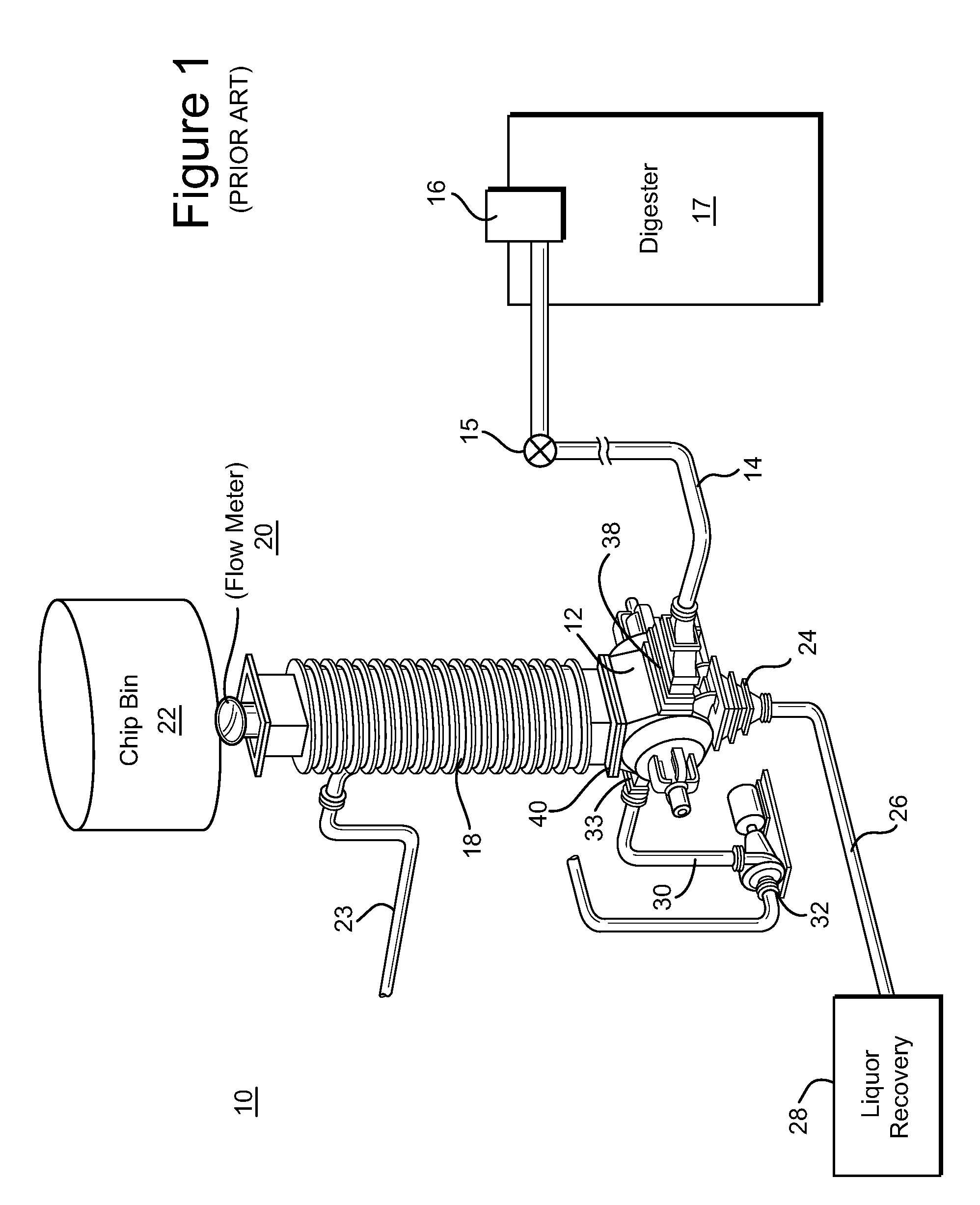
[0018]FIG. 1 is a schematic diagram of a conventional feed system 10 for providing a slurry of comminuted cellulosic material, e.g., wood chips, to a high pressure feeder (HPF) 12 and to a high pressure output conduit 14 leading to an inlet, e.g., a top separator 16, of a continuous digesting vessel 17. The HPF receives a low-pressure slurry or lo-level feed, via a chip chute 18, of comminuted cellulosic fibrous material (“chip slurry”) and outputs a high-pressure chip slurry. The high pressure slurry is suitable for introduction into a continuous digester, chip steaming vessel and other high pressure chip processing systems. A flow meter 15 may measure the rate of slurry flow through the output conduit 14 and to the inlet 16 of the digester 17.

[0019]The low pressure slurry is fed to the chip chute 18 through a chip flow meter 20 from a chip bin 22 or other chip supply system, such as shown in U.S. Pat. No. 5,622,598. Additional liquor may be added to the chip flow in the chip chute...


PUM


Abstract

A method and computer controlled apparatus to control fluid leakage in a high pressure feeder and a stationary housing with a chamber in which rotates a pocket rotor. The method includes: monitoring the fluid leakage from the high pressure feeder, wherein the fluid leakage is discharged from a low pressure outlet of the high pressure feeder; determining whether the fluid leakage is within a predefined range of acceptable fluid leakage, and moving the pocket rotor in the chamber to adjust the fluid leakage.

Description

RELATED APPLICATION[0001]This application claims the benefit of U.S. Provisional Patent Application Ser. No. 60 / 984,699 filed Nov. 1, 2007, the entirety of which is incorporated by reference.BACKGROUND OF THE INVENTION[0002]This invention relates to a method and system for feeding comminuted cellulosic fibrous material (“chips”) to a treatment vessel, such as a continuous digester which produces cellulosic pulp. This invention particularly relates to monitoring and adjusting a high pressure feeder.[0003]High pressure feeders (HPFs) transfer chips from a low pressure chip supply system to a high pressure system, such as a continuous digester system for chemical pulping of wood chips or other cellulosic material. HPFs are well-known and are described in, for example, U.S. Pat. No. 6,669,410. HPFs are a critical component of a continuous digester system in that they provide a high pressure slurry of wood chips and liquor to be fed to the digester vessel. Without the high pressure chip ...

Claims


Application Information

Patent Timeline
Patent Type & Authority Applications(United States)
IPC IPC(8): B65G53/30B65G53/40B65G53/46
CPCB65G53/4633B65G43/08
Inventor POPE, SCOTTLAAKSO, RICHARD O.LUHRMANN, CARLVOGEL, KEITH
Owner ANDRITZ INC
Features
  • R&D
  • Intellectual Property
  • Life Sciences
  • Materials
  • Tech Scout
  • Unparalleled Data Quality
  • Higher Quality Content
  • 60% Fewer Hallucinations
Learn More