
Rotary blower with noise abatement jacket enclosure

a technology of noise abatement and jacket enclosure, which is applied in the direction of rotary/oscillating piston pump components, machines/engines, liquid fuel engines, etc., can solve the problems of noise generation, 105 dba, and noisy rotary blowers, and achieves small size, light weight, and reduced noise transmission

Inactive Publication Date: 2009-06-04
HUANG PAUL XIUBAO +1
View PDF11 Cites 11 Cited by
  • Summary
  • Abstract
  • Description
  • Claims
  • Application Information

AI Technical Summary

Benefits of technology

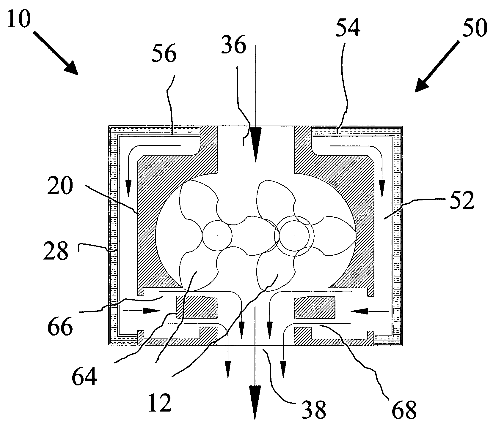
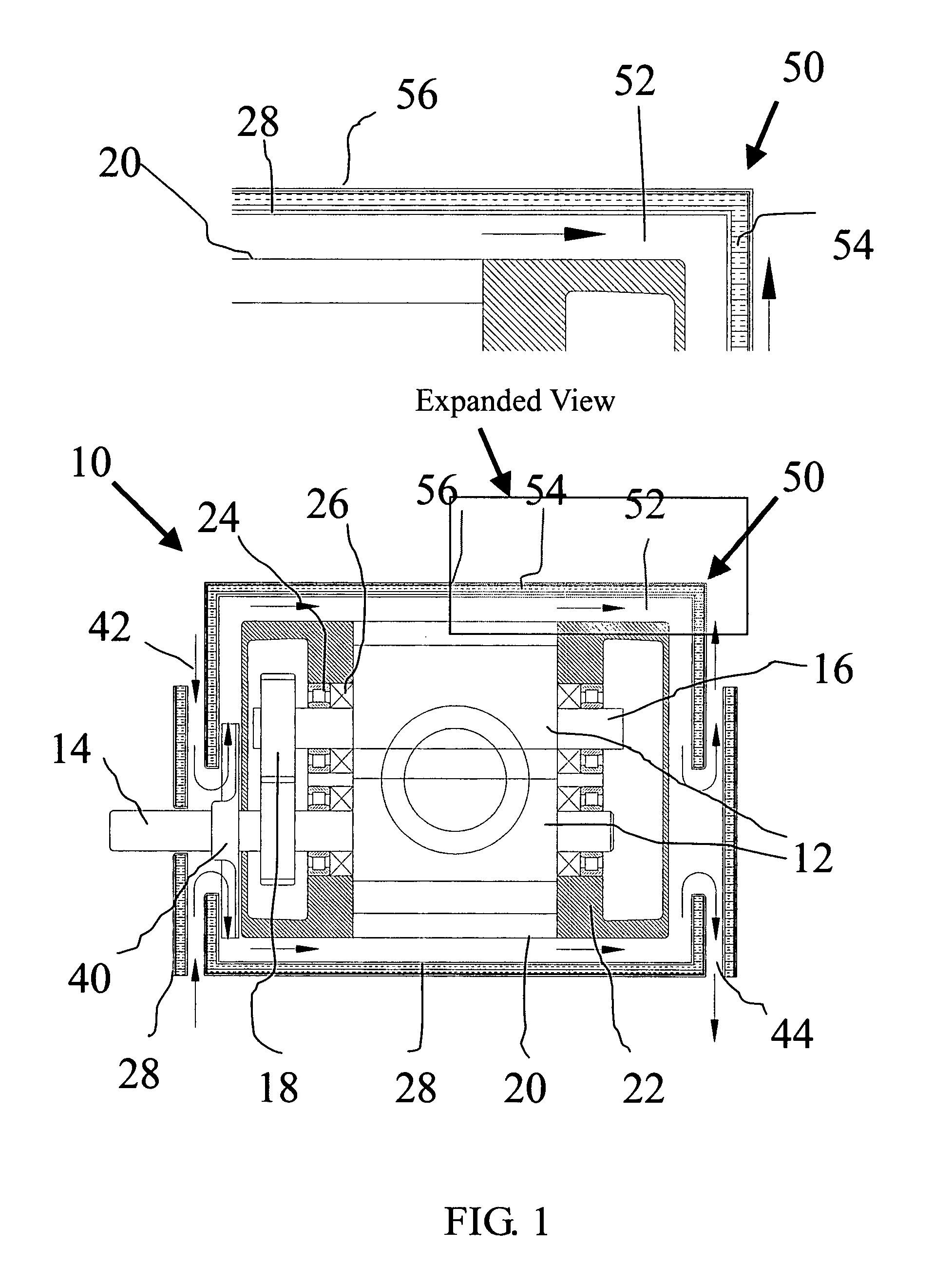
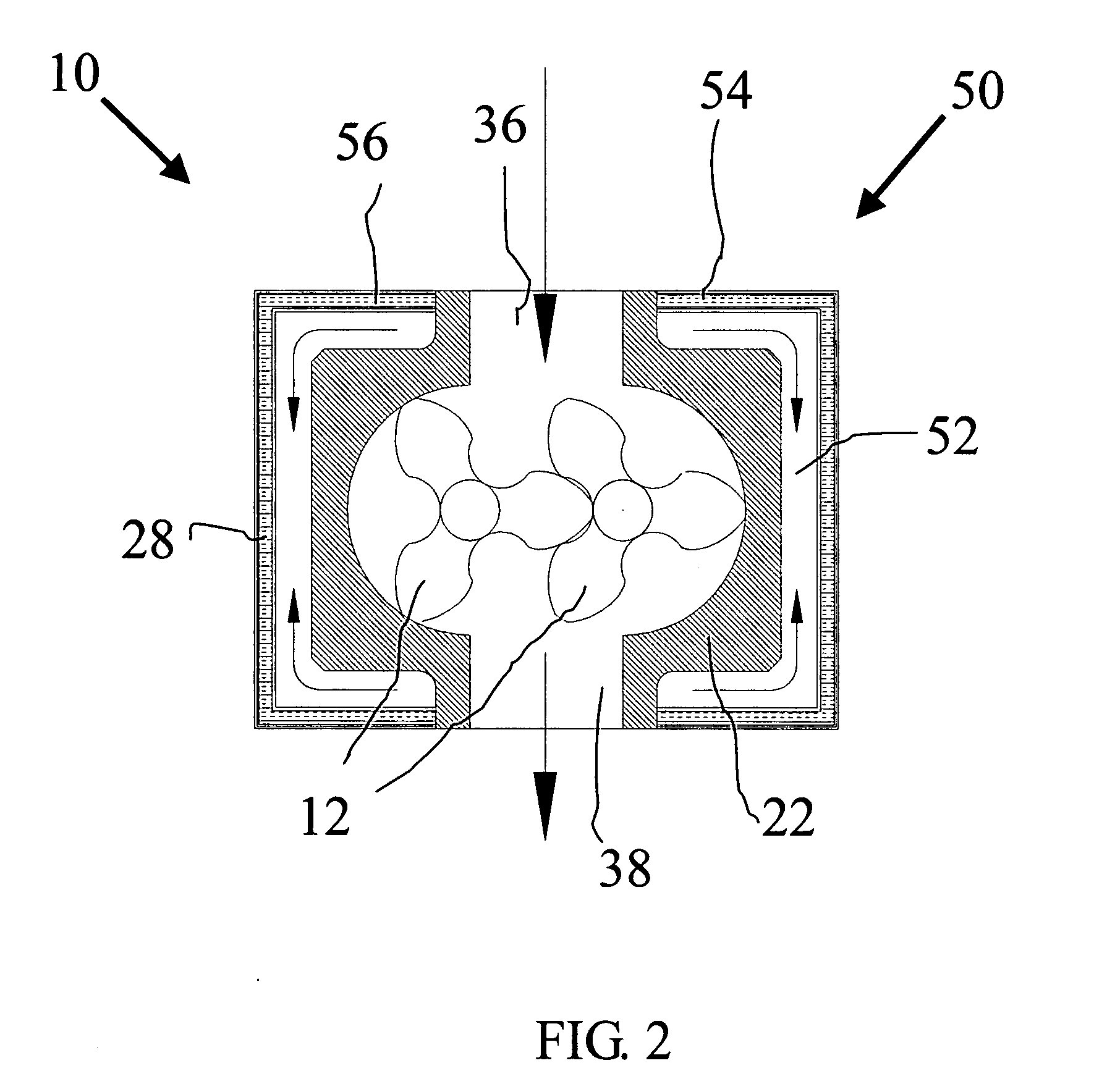
[0008]Accordingly, it is an object of the present invention to provide a noise abatement jacket enclosure, with a shape generally conforming to blower outer contours, for reducing noise transmission from a rotary blower while maintaining small size, light weight and suitable for mobile application.
[0009]It is a further object of the present invention to provide a noise abatement jacket enclosure for a rotary blower which comprises a forced air cooling jacket with a shape generally conforming to blower outer contours to enhance the heat transfer from the blower outer surfaces, so that they could operate more quietly, reliably and be used for mobile applications.

Problems solved by technology

Rotary blowers tend to be very noisy, sometimes as high as 90-105 dBA if untreated, because of the sharp discharge flow pulsations and engagement of timing gears at high speed.
From a system point of view, the primary source of noise generation in a blower package is the rotary blower.
In addition to the Rotary blower, there is an array of secondary sources of noise, such as the motor, the valves, and the silencer body.
However, its effectiveness is limited, only achieving 5-10 dBA reduction.
Such modification of the structure of the blower is expensive and can affect manufacturability of the blower.
Sound enclosure built in this fashion is generally very effective, reducing the noise levels up to 25 dBA, but it is expensive, heavy and bulky, especially not practical for mobile applications.

Method used


Image

  • Rotary blower with noise abatement jacket enclosure
  • Rotary blower with noise abatement jacket enclosure
  • Rotary blower with noise abatement jacket enclosure

Examples


Embodiment Construction

)

[0018]Although specific embodiments of the present invention will now be described with reference to the drawings, it should be understood that such embodiments are by way of example only and merely illustrative of but a small number of the many possible specific embodiments which can represent applications of the principles of the present invention. Various changes and modifications obvious to one skilled in the art to which the present invention pertains are deemed to be within the spirit, scope and contemplation of the present invention as further defined in the appended claims.

[0019]As a brief introduction, the present invention rotary blower with a noise abatement jacket enclosure includes an inner enclosed casing having a flow suction port and a flow discharge port and an internal bearing support structure, and an outer multi-layered cover, the noise abatement jacket enclosure, comprising a forced air cooling jacket layer, a sound absorbent layer, the inner surface in contact...


PUM


Abstract

A rotary blower with noise abatement jacket enclosure having multiple interconnected and synchronized parallel multi-lobe rotors with the same number of lobes for propelling flow from a suction port to a discharge port of an inner casing without internal compression. The noise abatement jacket enclosure is shaped to surround the blower and to conform generally to its body contours, but is oversized to provide adequate cooling spaces with outer skin of the blower. It comprises a forced air cooling jacket comprising an inner and outer cover, a sound absorbent layer comprising an inner and outer surface, the inner surface in contact with the blower outer cooling cover, and a sound barrier layer comprising an inner surface in contact with the outer surface of the sound absorbent layer.

Description

BACKGROUND OF THE INVENTION[0001]1. Field of the Invention[0002]The present invention relates generally to the field of mechanical vacuum pumps and blowers used in industrial and municipal applications, and more particularly relates to double rotor multi-lobe type blowers commonly known as positive displacement rotary blowers or simply Roots blowers, and more specifically relates to a Noise Abatement jacket enclosure for reducing noise transmission from rotary blowers.[0003]2. Description of the Prior Art[0004]Rotary blowers are widely used in industrial and municipal applications such as for loading a bulk truck by pneumatic conveying bulk materials or for cleaning municipal sewer lines by vacuum suction. They are desired because of its unique performance characteristics inherent from its rotary positive displacement nature: it delivers an almost constant flow at varying vacuum levels. The ability of varying pressure or vacuum at constant flow makes rotary blowers the ideal tools f...

Claims


Application Information

Patent Timeline
Patent Type & Authority Applications(United States)
IPC IPC(8): F04C18/12F04C29/06
CPCF04C18/126F04C29/066F04C29/04
Inventor HUANG, PAUL XIUBAOYONKERS, SEAN WILLIAM
Owner HUANG PAUL XIUBAO
Learn More