Networked Battery Monitors

a battery monitor and networked technology, applied in the field of battery monitors, can solve the problems of ineffective cost-effective installation of standalone battery monitors, inability to collect and trend battery data manually from remote sites, etc., and achieve the effect of reducing the cost of implementation

Active Publication Date: 2009-06-04
BTECH INC
View PDF25 Cites 138 Cited by
  • Summary
  • Abstract
  • Description
  • Claims
  • Application Information

AI Technical Summary

Benefits of technology

[0008]Referring to FIG. 1, this invention relates to hardware and software that allows the collection, management, and interpretation of data from multiple geographically separ

Problems solved by technology

Limited resources at many organizations make the collecting and trending of battery data manually from remote sites impractical.
On the other hand, the installat

Method used


Image

  • Networked Battery Monitors
  • Networked Battery Monitors

Examples


Embodiment Construction

[0038]The following detailed description discloses various embodiments and features of the invention. These embodiments and features are meant to be exemplary and not limiting.

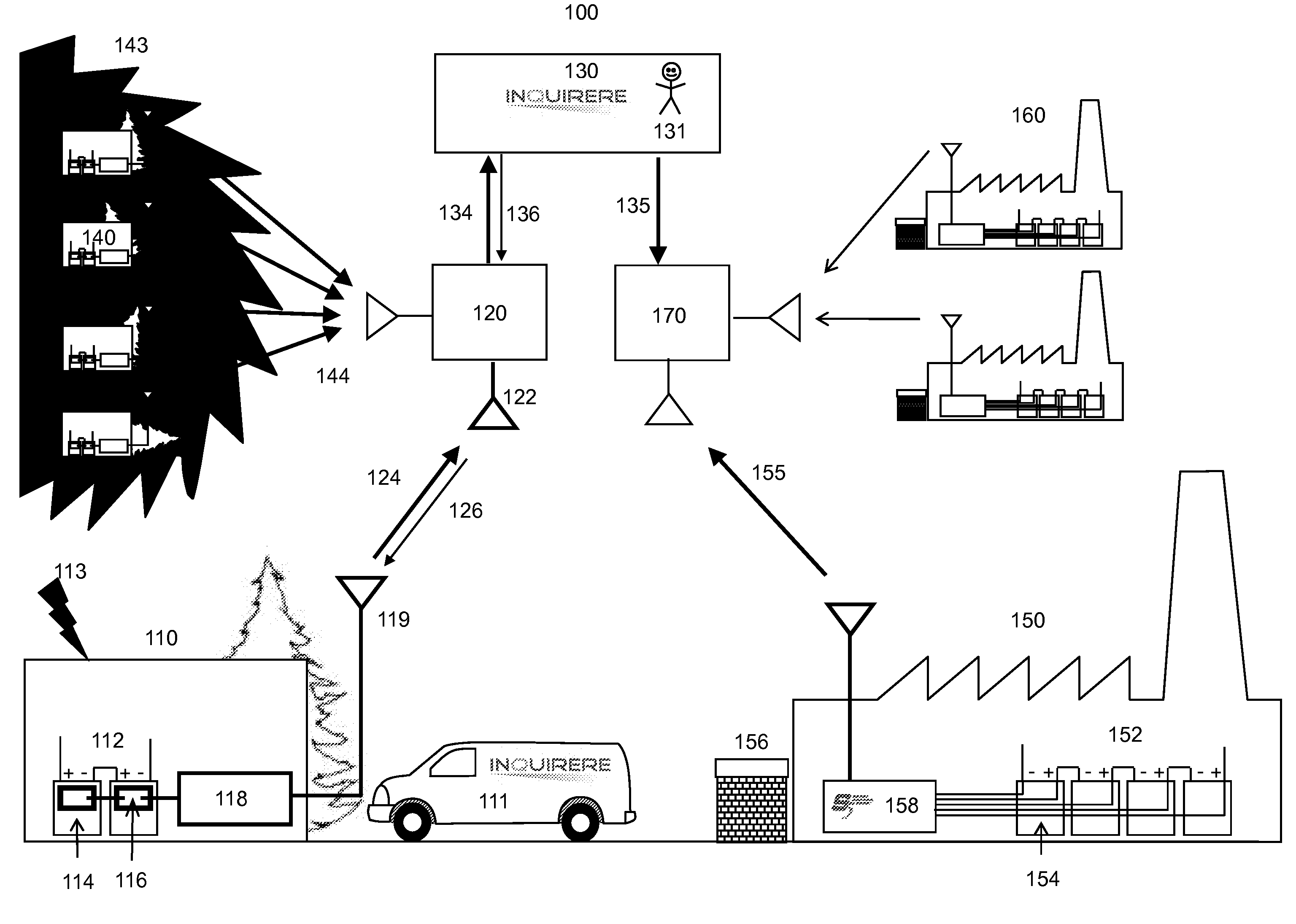
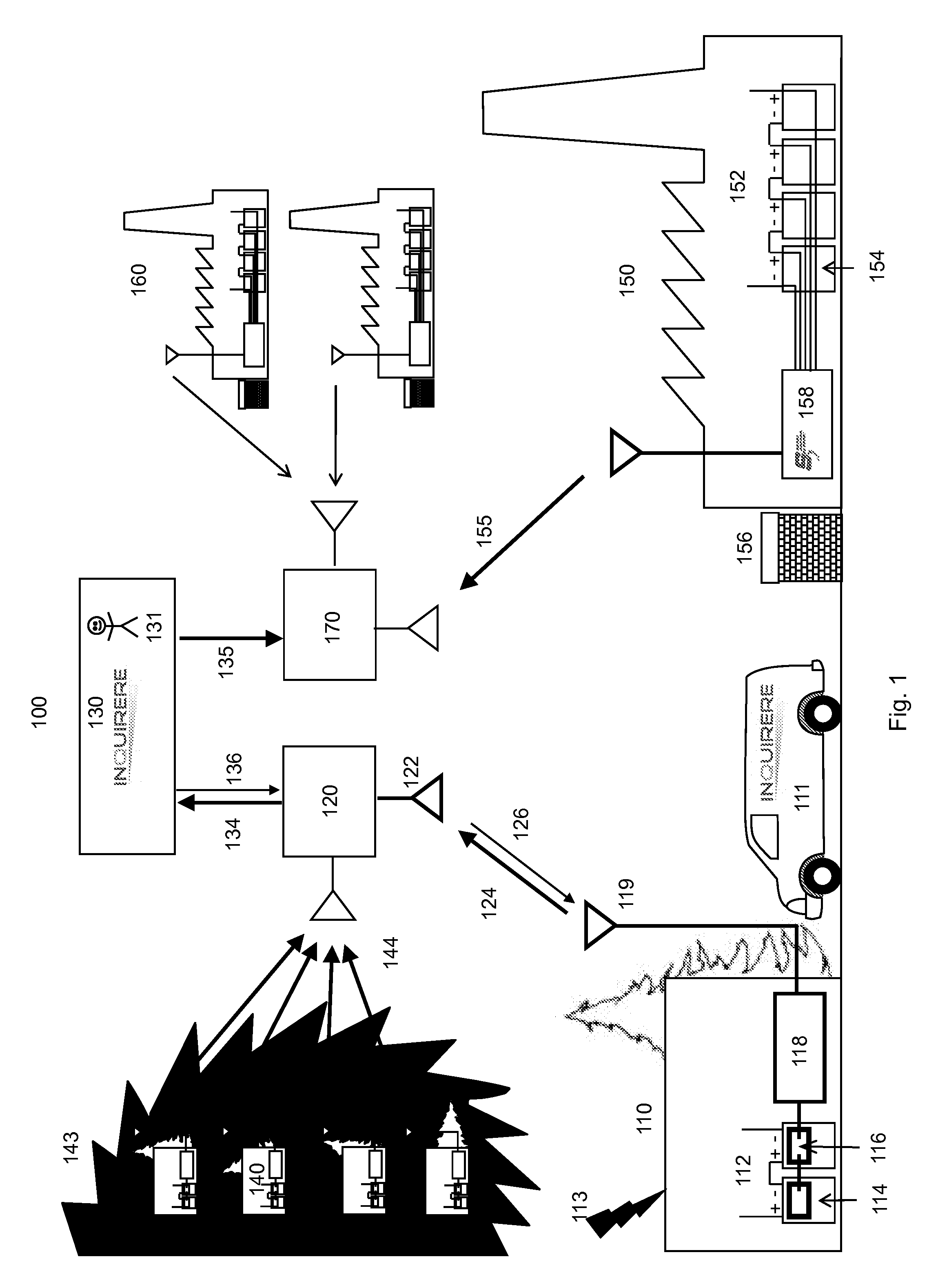
[0039]A networked battery monitor suitable for managing a widely dispersed set of batteries is illustrated in FIG. 1. FIG. 1 shows a remote location 110 with a monitored battery string 112 in communication with a battery management service 130 via a wireless telecom provider 120. FIG. 1 also shows an industrial installation 150 with a large battery string 152 also in communication with said battery management service via an alternative wireless telecom provider 170. The system may also include remote locations in communication with the battery management service via internet or other land line systems (not shown).

[0040]The battery string in the remote location has a relatively small number of cells (e.g. 1 to 100). Each of these cells has an associated individual battery monitor 116. The individual battery mon...


PUM


Abstract

A battery monitoring system for simultaneously managing the batteries in 100 or more remote locations, each of said locations comprising a battery string with 100 or fewer cells, said system comprising:
    • a. an individual battery monitor operatively engaged with at least one of said cells;
    • b. a network access module in communication with said battery monitor, said network access module comprising a modem compatible with an M2M data communication protocol, said protocol comprising assigning a variable IP address to said network access module modem upon initiation of a connection to a battery manager; and
    • c. said battery manager comprising a fixed IP address that can be connected to via said M2M data protocol upon said initiation of said connection,
wherein said network access module is programmed to periodically transfer battery monitor data, including ohmic measurements, to said battery manager at a frequency of not less than once per week and with a total rate of data transfer of not more than 1 Mb per month.

Description

CROSS REFERENCE TO RELATED APPLICATIONS[0001]This application claims priority to U.S. provisional patent application entitled “Networked Battery Monitors”, Ser. No. 60 / 991452 filed on Nov. 30, 2007. Said provisional application is incorporated herein by reference.TECHNICAL FIELD[0002]This invention is in the field of battery monitoringBACKGROUND ART[0003]Batteries comprising multiple cells in series and parallel are the primary source of energy in most standby power systems. The individual cells in these systems are commonly 2V lead acid VRLA cells. The cells are connected in series called a “battery string” in order to achieve the desired total voltage. A remote cell phone tower, for example, might have 24 cells connected in series to provide a 48V DC power supply. A centralized phone exchange (PBX) or Internet service provider (ISP) might have 240 cells in a string to provide 480 V power.[0004]In order to establish the viability of a lead acid battery to deliver power when require...

Claims


Application Information

Patent Timeline
IPC IPC(8): G01R31/36
CPCG01R31/3689H01M10/482H04Q9/00H04Q2209/756H04Q2209/40H04Q2209/823H04Q2209/10G01R31/371Y02E60/10
Inventor LEONARD, THOMAS J.PEDERSEN, GERGE A.POTEMPA, EDWARD M.BAUM, JR., ALLAN J.
Owner BTECH INC
Why Eureka
Try Eureka