Oil pan structure and an engine therewith

a technology of oil pan and structure, which is applied in the direction of casings, lubricant level maintenance, lubrication elements, etc., can solve the problems of insufficient stiffness of the structure, and high general engine vibration level, so as to enhance the natural frequency of engine as to engine bending deformation, avoid potential resonance vibration during engine operation, and enhance the rigidity of the oil pan

Active Publication Date: 2009-06-11
MITSUBISHI HEAVY IND LTD
View PDF6 Cites 18 Cited by
  • Summary
  • Abstract
  • Description
  • Claims
  • Application Information

AI Technical Summary

Benefits of technology

[0088]Therefore, a natural frequency of the engine as to engine bending deformation can be enhanced because of the bead reinforcement effect and press-work hardening. Further, by means of adjusting the amplitude and period of the substantially triangular wave-grooves, a potential resonance vibration during engine operation can be avoidable; in particular, the rigidity of the right-side and left-side walls, by extension, the whole oil pan rigidity is enhanced.
[0089]In a preferable example according to the present invention, a

Problems solved by technology

In many cases, such an oil pan is manufactured by means of welding thin sheets of metal; thus, the stiffness of the structure is not sufficient.
Further, the engine vibration level is high in general.
Thus, the stiffness of the structure is not sufficient; further, the engine vibration level is high in general.
However, in the mentioned measures according to conv

Method used


Image

  • Oil pan structure and an engine therewith
  • Oil pan structure and an engine therewith
  • Oil pan structure and an engine therewith

Examples


Embodiment Construction

[0131]Hereafter, the present invention will be described in detail with reference to the embodiments shown in the figures. However, the dimensions, materials, shape, the relative placement, and so on of a component described in these embodiments shall not be construed as limiting the scope of the invention thereto, unless especially specific mention is placed.

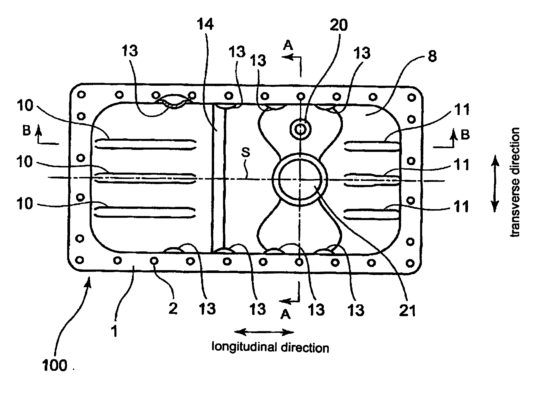
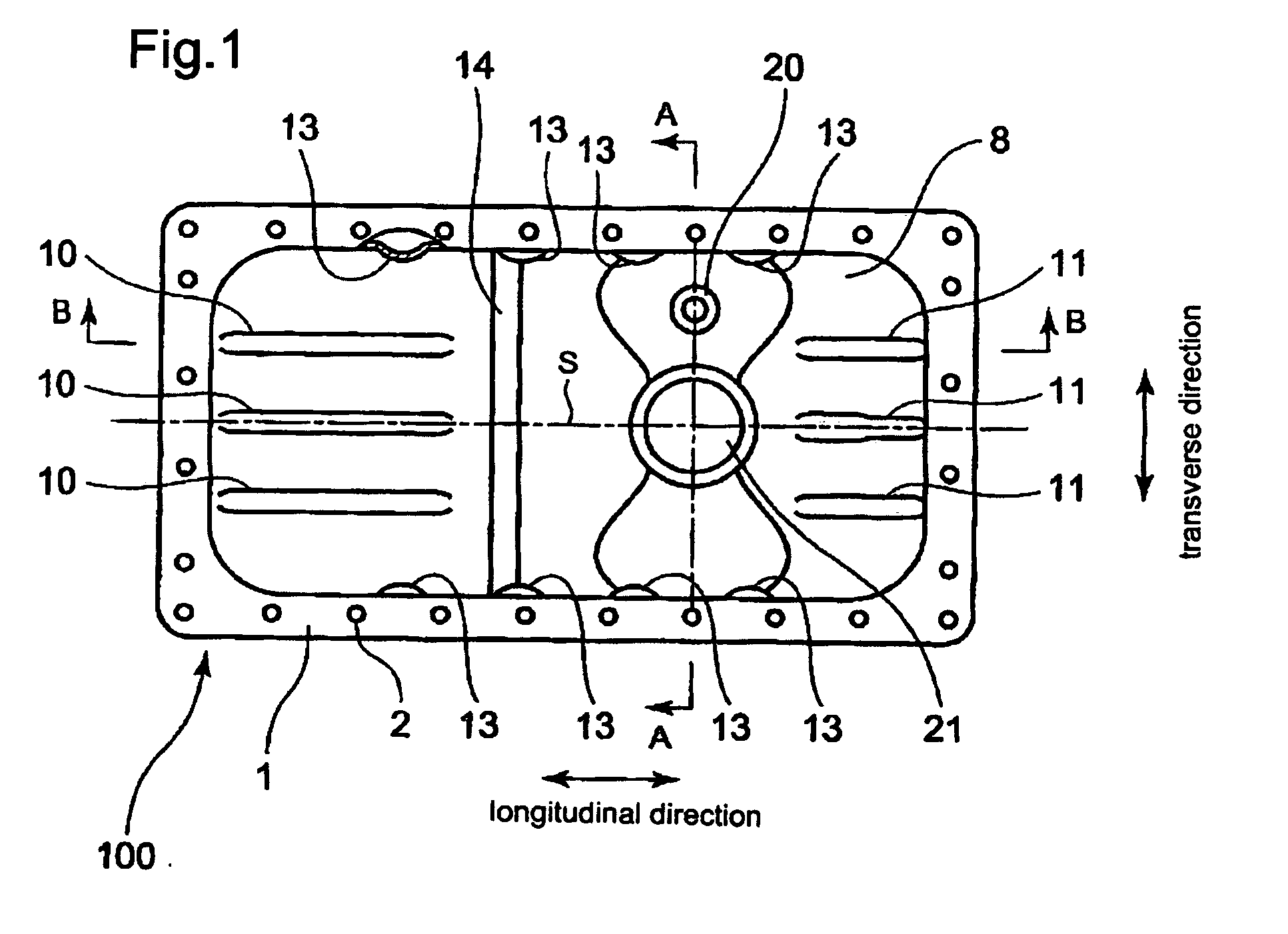
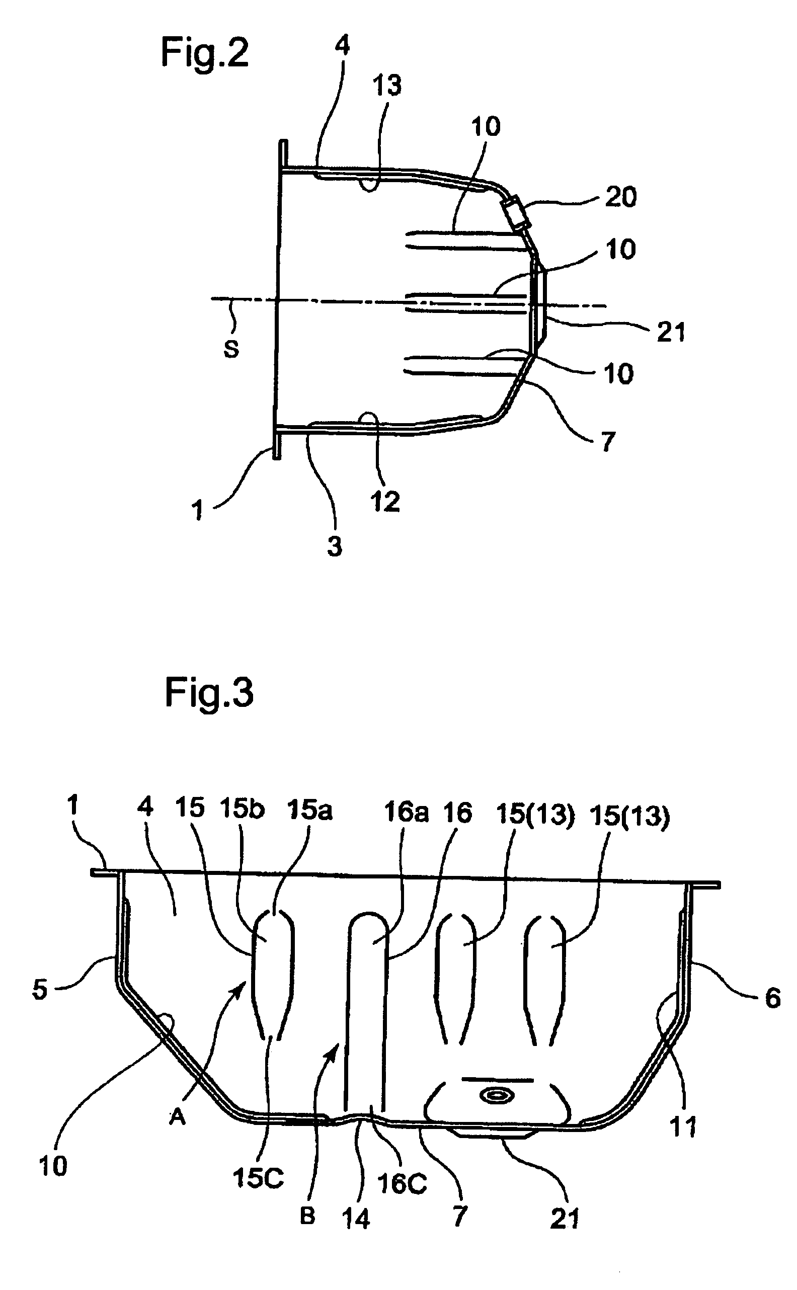
[0132]FIG. 1 shows a top view of an oil pan for small general-purpose engines as to embodiments of the present invention; FIG. 2 shows a sectional view along the A-A section in FIG. 1 as to the first embodiment; and FIG. 3 shows a sectional view along the B-B section in FIG. 1 as to the first embodiment.

[0133]In FIGS. 1 to 3, the numeral 100 denotes an oil pan; the structure thereof is as follows.

[0134]The oil pan 100 comprises:

[0135]an oil pan flange 1 that is fastened with a plurality of bolts 2 to the undersurface of an engine crankcase (not shown);

[0136]a bottom wall 7 that forms a bottom part of the engine;

[0137]two side w...


PUM


Abstract

An oil pan structure includes a plurality of reinforcement beads of several kinds. An engine utilizes the oil pan, whereby the strength and vibration-rigidity (rigidity against vibration) of the oil pan and the engine are sufficiently enhanced so that a natural frequency of the oil pan and the engine therewith becomes adjustable through a selection as to the numbers, locations, and sizes of the beads.

Description

BACKGROUND OF THE INVENTION[0001]1. Field of the Invention[0002]The present invention relates to an oil pan structure and an engine therewith whereby the structure comprises: an oil pan flange; a bottom wall that forms a bottom part of an engine; two side walls (i.e. a left side wall and a right side wall) along a longitudinal direction of the engine, each wall that communicates a longitudinal edge of the bottom wall with the oil pan flange; and two side walls (i.e. a front side wall and a rear side wall) along a transverse direction of the engine, each wall that communicates a transverse edge of the bottom wall with the oil pan flange, thereby, the structure forms a boxy space, being capable of storing engine-internal oil therein.[0003]2. Description of the Related Art[0004]An oil pan structure itself is a public known art, the structure comprising: an oil pan flange that is fastened with bolts to the undersurface of the crankcase; a bottom wall that forms a bottom part of an engin...

Claims


Application Information

Patent Timeline
IPC IPC(8): F01M11/06F01M11/00
CPCF01M11/0004F01M2011/002F01M2011/0008
Inventor ISHII, YUKIYOSHIZUMI, KAZUHIROSUGANUMA, NAOKITAKAHASHI, SHINICHIROSUZUKI, RYO
Owner MITSUBISHI HEAVY IND LTD
Why Eureka
Try Eureka