Oil pan structure

a technology of oil pans and oil pans, which is applied in the direction of oil pumps, lubrication elements, mechanical equipment, etc., can solve the problems of not being able to suppress the temperature rise of such oil, and achieve the effects of high viscosity, low viscosity and high viscosity

Inactive Publication Date: 2009-06-11
TOYOTA BOSHOKU KK
View PDF9 Cites 23 Cited by
  • Summary
  • Abstract
  • Description
  • Claims
  • Application Information

AI Technical Summary

Benefits of technology

[0038]According to the oil pan structure of the present invention, when returning oil from the internal combustion engine that has fallen onto the baffle plate has a high temperature, the oil has a comparatively low viscosity, and thus, the oil passes through the upper communication opening provided in the baffle plate and then transits the bottom wall of the oil pan main body after falling into the first area. The heat of the oil is dissipated by coming into contact with the oil cooling portion that is provided at the bottom wall, and the oil passes through the lower communication opening at a lower end side of the partitioning wall to reach the second area. Then, the oil is drawn into the oil suction opening. In addition, when the returning oil from the internal combustion engine has a low temperature, the oil has a comparatively high viscosity, and thus the oil does not readily pass through the upper communication opening. The oil continues flowing along the incline of the baffle plate, reaches the second area after falling from an end portion of the baffle plate, and is drawn into the oil suction opening without transiting the oil cooling portion. In this manner, when the temperature of the oil is high, the oil transits the bottom wall of the oil pan main body so that the heat of the oil is dissipated by coming into contact with the oil cooling portion. Thus, the heat of the high-temperature oil can be efficiently dissipated. In contrast, when the temperature of the oil is low, the oil is drawn into the oil suction opening without being cooled, and the circulated quantity of oil is reduced by prioritizing the circulation of the oil in the second area. Thus, the temperature of the low-temperature oil can be rapidly raised, and it is possible to realize the early warm-up of the internal combustion engine.
[0039]Moreover, in the case in which the oil cooling portion includes a groove portion that extends from the first area toward the oil retaining portion, a surface area of the oil cooling portion, with which the oil that has passed through the upper communication opening and fallen into the first area comes into contact, becomes large. Therefore, the heat of the high-temperature oil can be efficiently dissipated.
[0040]Furthermore, in the case in which the part of the bottom wall of the oil pan main body that corresponds to the lower portion of the second area includes a heat insulating function, the heat of the oil when the oil has a low temperature does not readily dissipate even after coming into contact with the bottom wall at the lower portion of the second area. Thus, the temperature of the low-temperature oil can be raised even more rapidly, and it is possible to realize an even earlier warm-up of the internal combustion engine.
[0041]In addition, in the case in which a ribbed heat dissipating plate is provided on the outer side of the bottom wall of the oil pan main body, heat dissipation effect on the high-temperature oil that passes through the upper communication opening and falls into the first area can be further improved.
[0042]Furthermore, in the case in which the first area is provided on at least both sides of the second area, the oil retaining portion, which has the oil suction opening disposed thereabove, is disposed at a center portion of oil paths that are provided on both sides. Therefore, the oil is readily guided to the oil retaining portion.
[0043]In addition, in the case in which the cover member is provided above the baffle plate, the high-temperature returning oil from the internal combustion engine can be prevented from falling directly into the second area.

Problems solved by technology

Oil that has been drawn back into the oil strainer without coming into contact with the outer wall is also present, and thus it is not possible to suppress a rise in the temperature of such oil.

Method used


Image

  • Oil pan structure
  • Oil pan structure
  • Oil pan structure

Examples


embodiments

[0065]Below, an oil pan structure of the present invention will be explained in detail using embodiments, with reference to the drawings. Note that an oil pan structure that is provided at a lower portion of an internal combustion engine is illustrated as the oil pan structure of the present embodiment.

(1) Configuration of the Oil Pan Structure

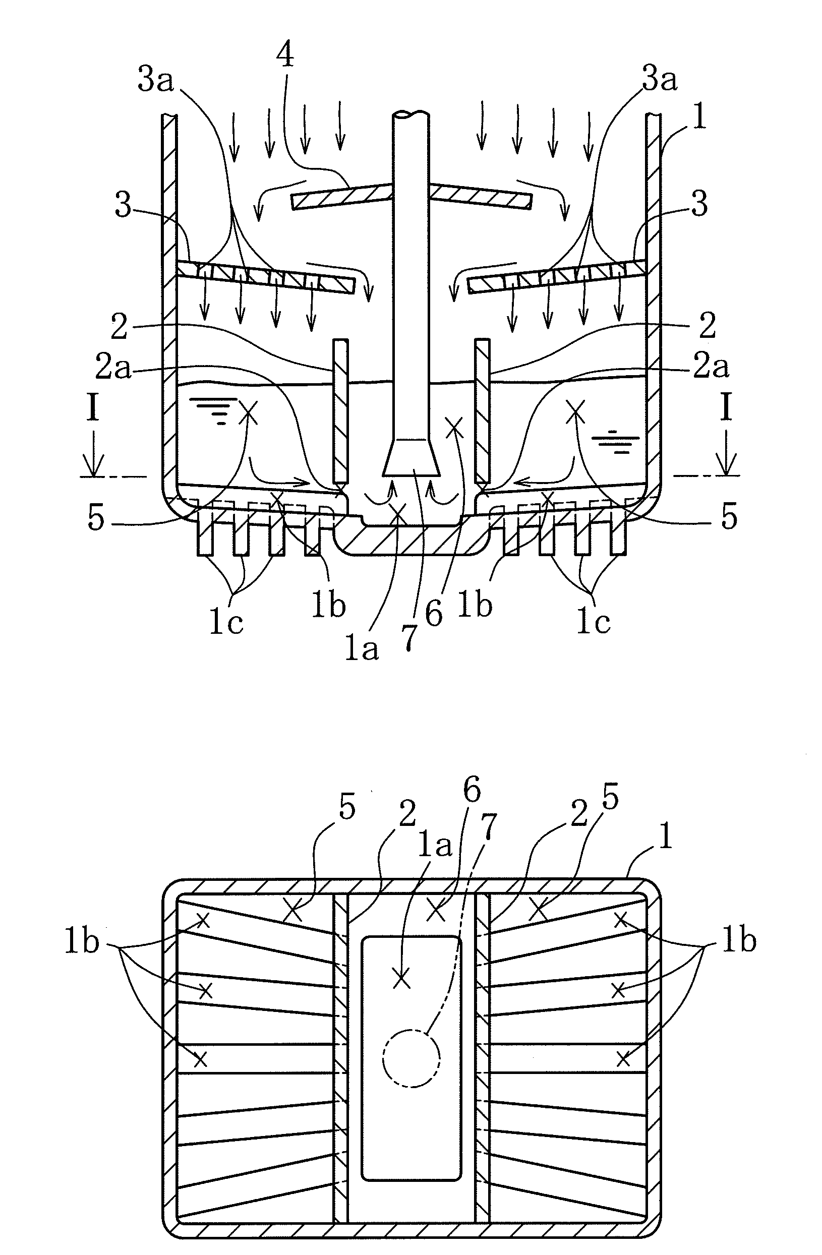
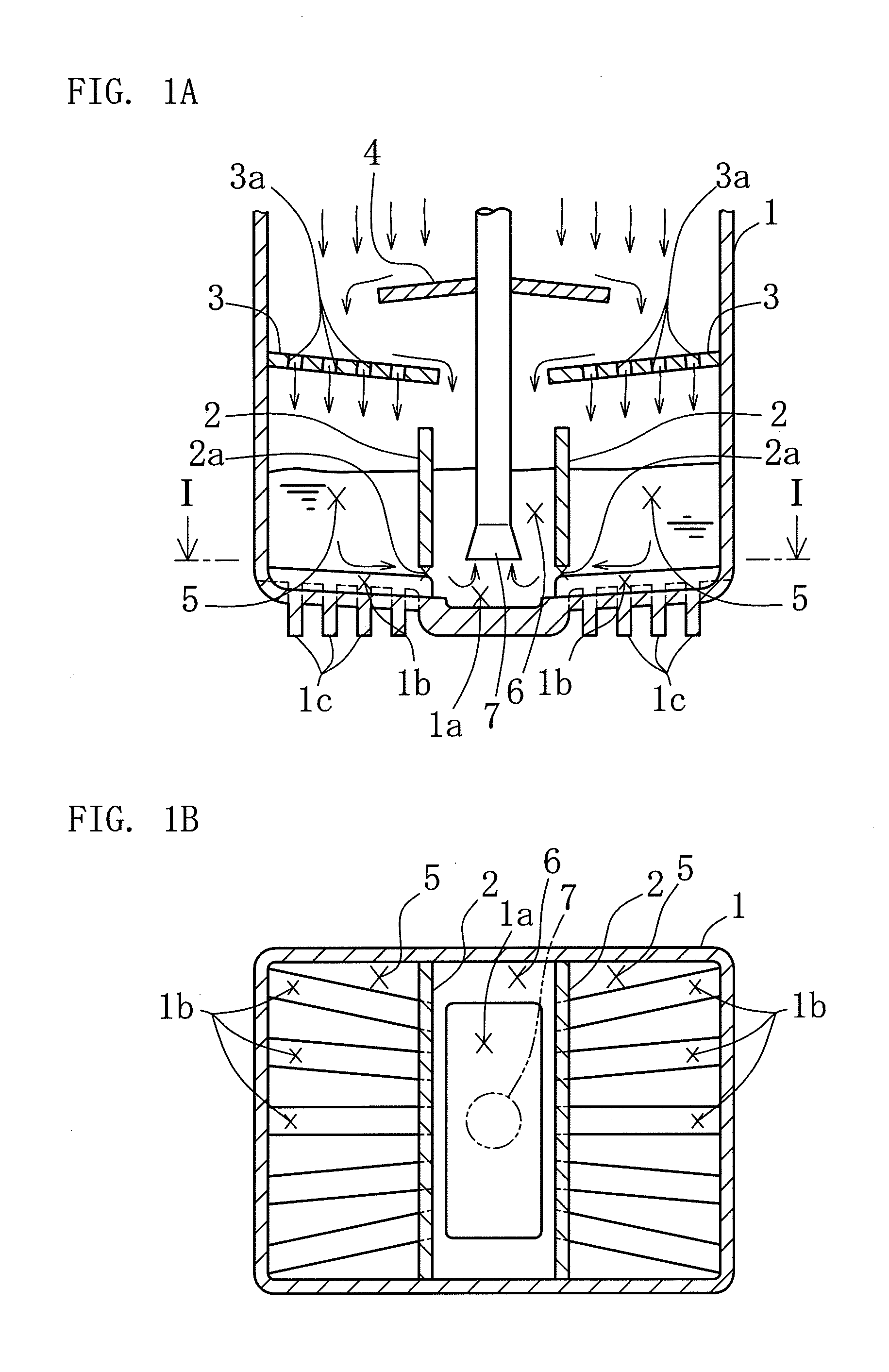
[0066]As shown in FIGS. 1A and 1B, the oil pan structure of the present embodiment is provided with an oil pan main body 1. In the oil pan main body 1, two plate-shaped partitioning walls 2 are provided, and both ends thereof are attached to side walls of the oil pan main body 1. The inside of the oil pan main body 1 is partitioned, by the two partitioning walls 2, into a second area 6 between the two partitioning walls 2 and first areas 5 on both sides of the second area 6, such that the volume ratio between the first areas 5 and the second area 6 is about 3:1. An oil suction opening 7, which is provided with an oil strainer at a distal end t...


PUM


Abstract

An oil pan structure is provided that can prevent overheating when the temperature of oil is high, and can rapidly raise the temperature when the temperature of the oil is low. The oil pan structure includes: an oil pan main body; a partitioning wall that partitions the inside of the oil pan main body into a first area and a second area; a plate-shaped baffle plate that is provided at an upper portion of the oil pan main body and inclines downward from the first area toward the second area. The oil pan structure further includes: an oil retaining portion at a lower portion of the second area and an oil cooling portion at a lower portion of the first area, at the bottom wall of the oil pan main body; an upper communication opening that communicates an upper surface side and a lower surface side thereof in the baffle plate; a lower communication opening at a lower end side of the partitioning wall that communicates the first area and the second area as well as causes oil that has fallen into the first area after passing through the upper communication opening to flow into the second area via the oil cooling portion.

Description

BACKGROUND OF THE INVENTION [0001]1. Field of the Invention[0002]The present invention relates to an oil pan structure, and in particular, relates to an oil pan structure that can prevent overheating when an oil temperature is high by providing, at a lower portion of the oil pan, a cooling portion through which substantially an entire quantity of oil that is fed into an internal combustion engine passes, and that can quickly raise the oil temperature when it is low.[0003]2. Description of the Related Art[0004]In recent years, temperature control of oil that is used in lubrication of internal combustion engines has become important. This is because the temperature and the viscosity of oil are correlated, and the viscosity of the oil must be maintained within a constant range in order to maintain a constant oil film thickness. In addition, the oil that is discharged from the lubrication paths of the internal combustion engine during use normally acquires a temperature that is higher t...

Claims


Application Information

Patent Timeline
Patent Type & Authority Applications(United States)
IPC IPC(8): F16N31/00
CPCF01M11/0004F01M2011/0045F01M2011/0025
Inventor HIRAMATSU, CHIAKI
Owner TOYOTA BOSHOKU KK
Why Eureka
Try Eureka