
Collapsible support apparatus and methods

a support apparatus and collapsible technology, applied in the direction of dismountable cabinets, movable shelf cabinets, packaged goods types, etc., can solve the problems of drying up and dying off, and achieve the effects of preventing back strain, reducing handling labor or possibly even potential damage to plants, and promoting optimal root growth

Inactive Publication Date: 2009-06-11
TAGAWA GREENHOUSE ENTERPRISES
View PDF82 Cites 9 Cited by
  • Summary
  • Abstract
  • Description
  • Claims
  • Application Information

AI Technical Summary

Benefits of technology

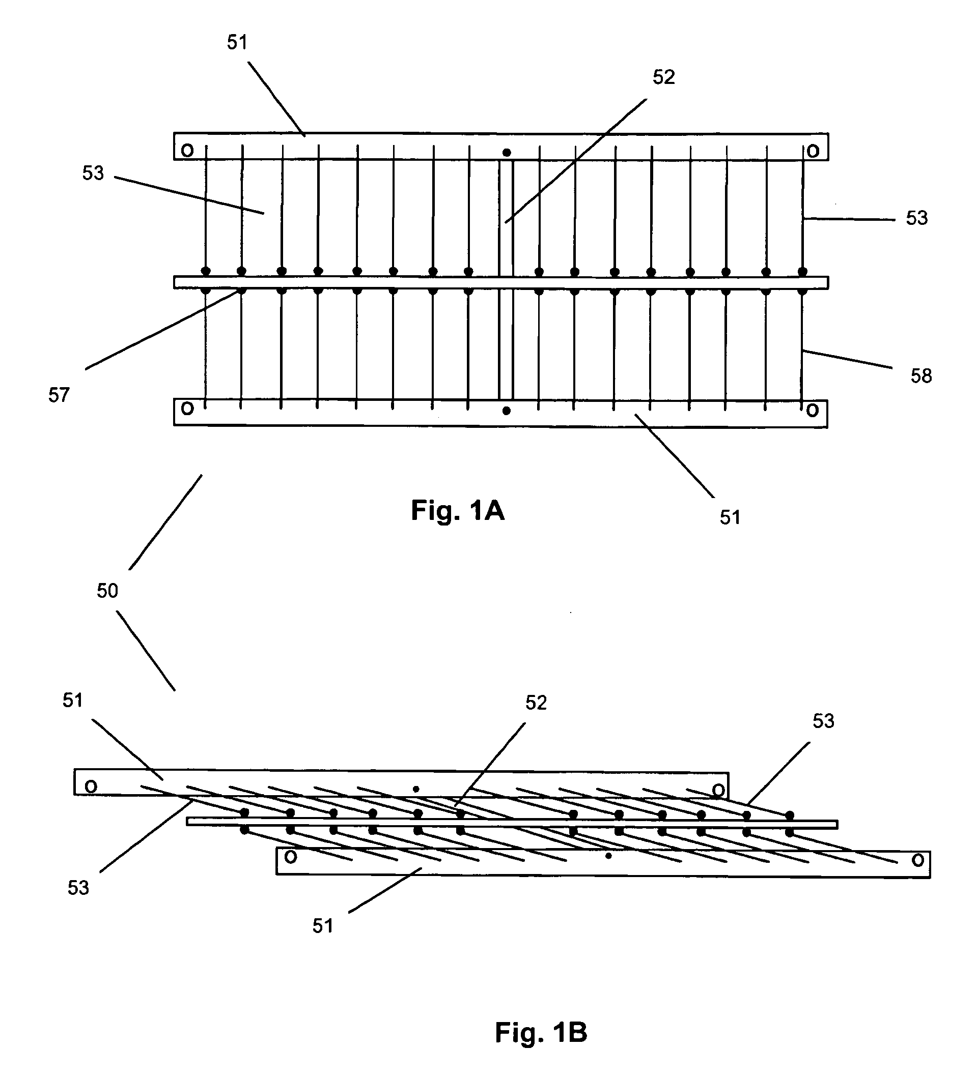
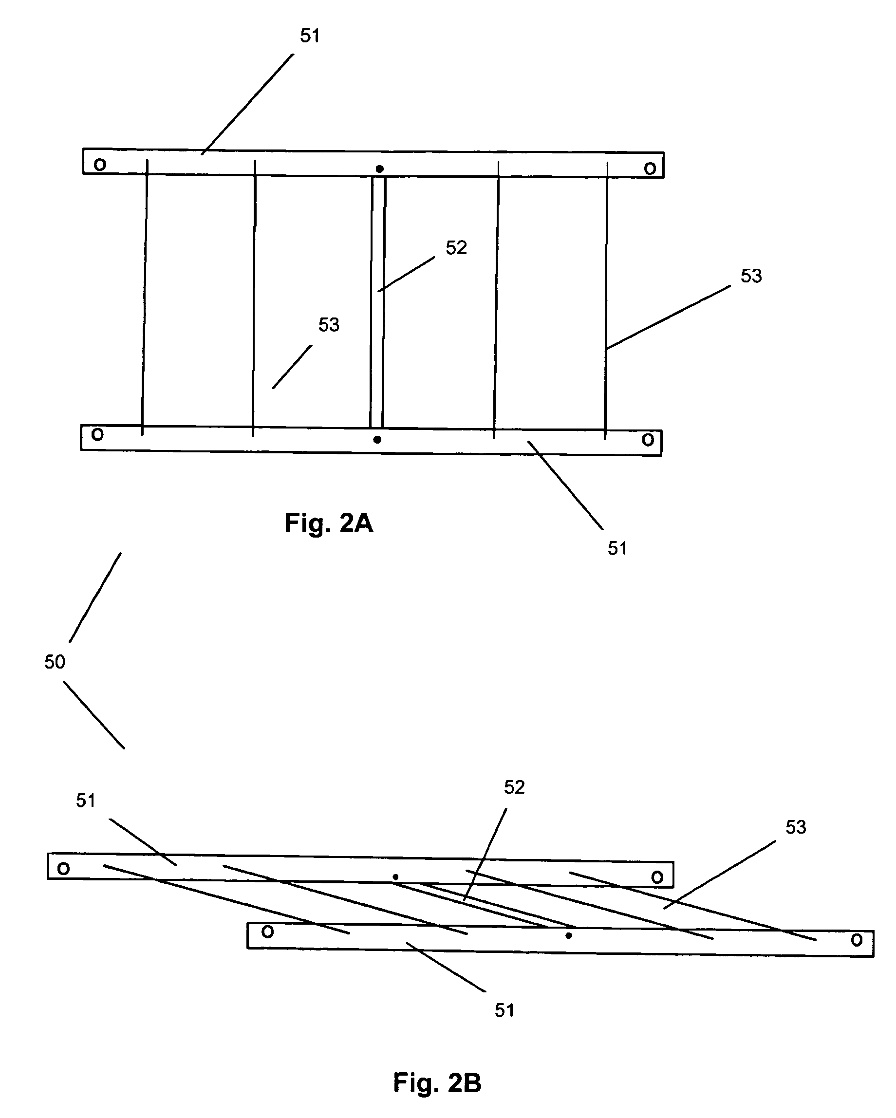
[0013]In various embodiments, a support apparatus (an apparatus such as a rack that may be used to support one or more items) may allow users to quickly and easily reduce the size of the racks, such as by collapsing the racks, for reduced transportation and storage costs.
[0014]In a multiple layer rack system (where apparatus are stacked upon one another), each layer may be able to be set out individually (whether established on a conventional support (e.g., a table) or not), perhaps allowing a punched plant producer to grow plants and a manufacturer to assemble, produce, or inspect the goods easily prior to or after shipping. Each layer may have feet which may be variable in height, perhaps allowing for the correct air flow beneath the layer to encourage optimum root growth on a plant growing on the layer (whether before or during shipment), or perhaps even to provide the correct height for a manufacturer assembling, inspecting, or displaying goods. The height of the layer may also be varied to an optimum height, for example to prevent back strain on workers handling products on the bench, or, during shipment, to allow for an optimum airflow beneath the support rack and the items supported thereby. The entire layer perhaps may be picked up, such as perhaps to reduce handling labor or possibly even potential damage to plants or goods. Layers then may be readily stacked, perhaps creating a distribution system that may allow for efficient and possibly less expensive transportation. The distance between each layer may also be varied, perhaps to maximize the efficiency of the distribution system while protecting the product, and optimize airflow. This may also allow for quick and easy packing and unpacking of the plants or goods. When utilizing the rack, many plants or goods might not require any other packing materials, and perhaps could be shipped “loose” on the rack system, thereby perhaps further reducing disposal costs and increasing efficiencies.
[0015]Growing punched plants, such as PUNCHABLES® brand plants, may require a correct ratio of root to shoot (perhaps as noted in U.S. Pat. No. 6,779,300, issued Aug. 24, 2004, and U.S. Pat. No. 7,069,693, issued Jul. 4, 2006, each hereby incorporated herein by reference). The rack system may provide the correct air flow beneath a punched plant tray, such as a PUNCHABLES® brand tray, to cause air root pruning. Air root pruning may occur when roots come into contact with sufficient air and air movement perhaps to cause them to dry up and die off. Air root pruning may be critical to cause punched plant plugs, such as PUNCHABLES® brand plugs, to form a desired heavy root system due to the naturally occurring branching that may take place with roots when roots dry and die off. The space between the layers of the rack system, whether on the floor and being used as a bench or stacked together to form a multiple layer rack system, may be determined by the length of the feet of a particular layer. In some embodiments, to most effectively maximize space utilization between layers and most effectively utilize the air flow beneath a punched plant tray, such as a PUNCHABLES® brand tray, the length of the feet may range from between 3 inches for very small plants and as much as 24 inches for larger plants.

Problems solved by technology

Air root pruning may occur when roots come into contact with sufficient air and air movement perhaps to cause them to dry up and die off.

Method used


Image

  • Collapsible support apparatus and methods
  • Collapsible support apparatus and methods
  • Collapsible support apparatus and methods

Examples


Embodiment Construction

[0053]As mentioned earlier, the present inventive technology includes a variety of aspects, which may be combined in different ways. The following descriptions are provided to list elements and describe some of the embodiments of the present inventive technology. These elements are listed with initial embodiments, however it should be understood that they may be combined in any manner and in any number to create additional embodiments. The variously described examples and preferred embodiments should not be construed to limit the present inventive technology to only the explicitly described systems, techniques, and applications. Further, this description should be understood to support and encompass descriptions and claims of all the various embodiments, systems, techniques, methods, devices, and applications with any number of the disclosed elements, with each element alone, and also with any and all various permutations and combinations of all elements in this or any subsequent ap...


PUM


Abstract

Methods and apparatus may permit the propagation and distribution of plants, or merely storage and / or shipment of items, in a space efficient manner. Individual apparatus may be stacked in a rack system. Space between individual stacked apparatus may be varied to accommodate plants of various sizes and permit varying degrees of air flow. Individual apparatus may be collapsed into smaller units without removable hardware and with all components remaining connected at all times. Apparatus may be delivered in a fully assembled stated and returned in a state of reduced size, minimizing transportation costs and efficiently utilizing transportation resources.

Description

[0001]This US non-provisional patent application claims priority to U.S. Provisional Patent Application 60 / 992,617, filed Dec. 5, 2007, said provisional application hereby incorporated herein by reference.BACKGROUND OF THE INVENTION[0002]Generally, the inventive technology may involve a support apparatus (e.g., a type of rack) for storing and / or shipping plants or other goods; the apparatus may be reduced in size upon collapsing from a support configuration to a collapsed configuration, thereby occupying less space, so that shipping or storing the apparatus is economical. The apparatus may be particularly suited for use with punched plant growing techniques, as exemplified perhaps by PUNCHABLES® brand systems and products, or perhaps as described in or related to any of U.S. Pat. No. 6,184,449, issued Feb. 6, 2001, U.S. Pat. No. 6,723,839, issued Apr. 20, 2004, U.S. Pat. No. 6,779,300, issued Aug. 24, 2004, U.S. Pat. No. 6,915,607, issued Jul. 12, 2005, U.S. Pat. No. 7,069,693, issu...

Claims


Application Information

Patent Timeline
IPC IPC(8): A47B47/00A47B43/00
CPCA01G31/06B65D2519/0097B65D85/52B65D2519/00024B65D2519/00029B65D2519/00034B65D2519/00059B65D2519/00064B65D2519/00069B65D2519/00273B65D2519/00293B65D2519/00298B65D2519/00323B65D2519/00338B65D2519/00562B65D2519/00572B65D2519/00761B65D2519/0087B65D19/0097Y02P60/21
Inventor TAGAWA, RANDALL E.HENWOOD, RICHARD D.
Owner TAGAWA GREENHOUSE ENTERPRISES
Learn More