
Two-hand switch device

a switch device and hand technology, applied in frequency-division multiplexes, instruments, manufacturing tools, etc., can solve the problems of excessive fatigue of workers, excessive burden on workers for each activation, and worker temptation to resort to improper modes of operation, etc., to achieve low load, not causing excessive fatigue to workers, and high reliability

Inactive Publication Date: 2009-06-11
ORMON CORP +2
View PDF3 Cites 5 Cited by
  • Summary
  • Abstract
  • Description
  • Claims
  • Application Information

AI Technical Summary

Benefits of technology

[0038]The present invention thus provides a two-hand switch device that requires a small load for each operation cycle, and does not cause excessive fatigue to the worker even after a large number of cycles of operation. Also, the present invention provides a highly reliable two-hand switch device that would not activate by any improper mode of operation other than by a proper mode of operation using the both hands of a worker. Further, the present invention provides a two-hand switch device than can accurately identify the worker who actually operated the two-hand switch device.DETAILED DESCRIPTION OF THE PREFERRED EMBODIMENT(S)
[0039]Preferred embodiments of the two-hand switch device of the present invention are described in the following in more detail with reference to the appended drawings.
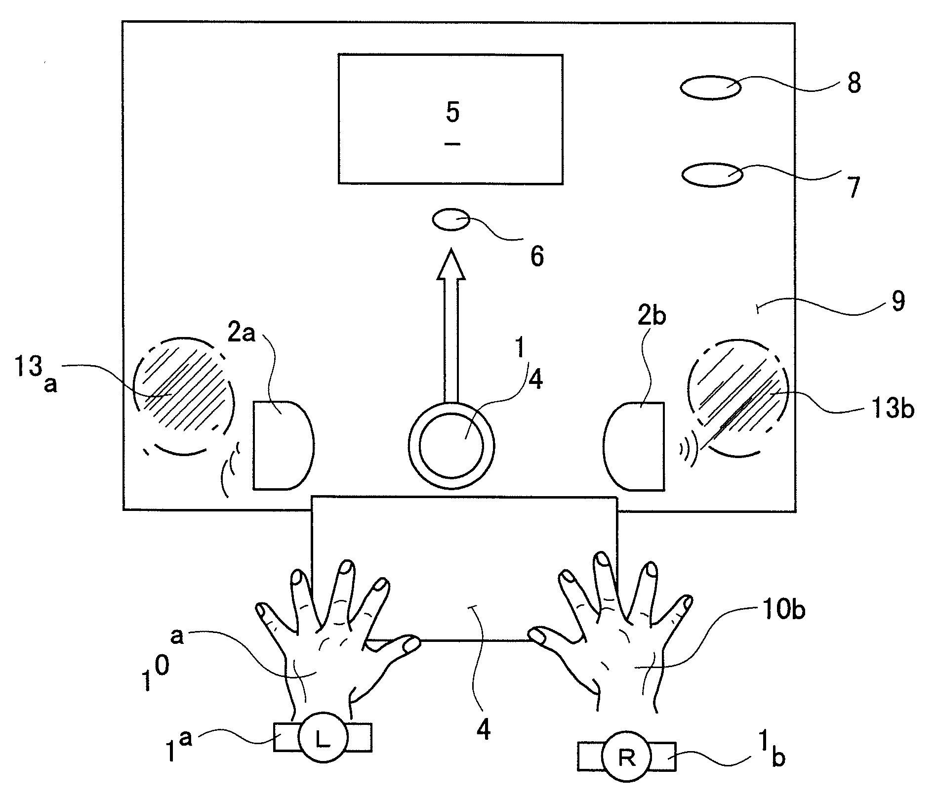
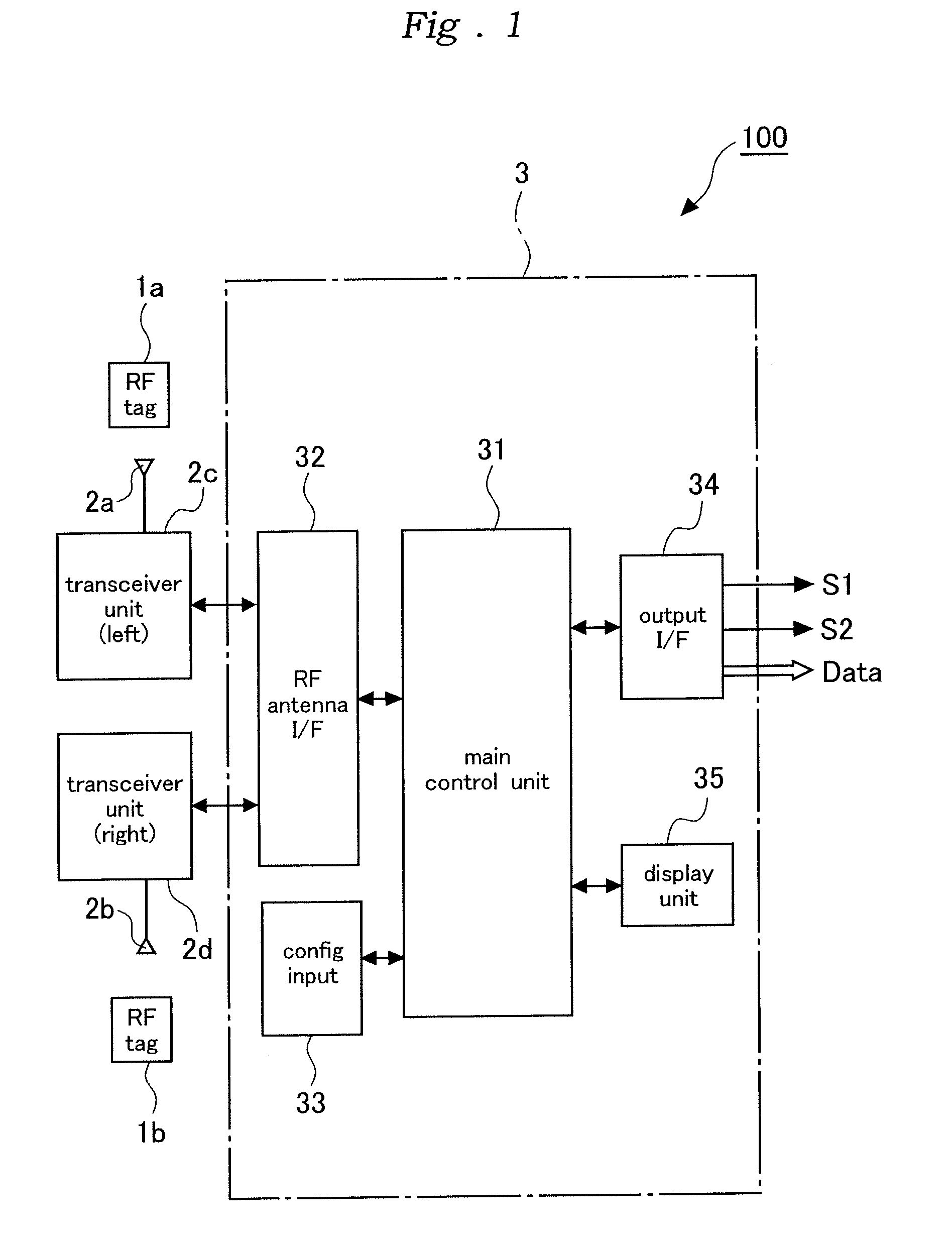
[0040]FIG. 1 shows a hardware diagram of an exemplary two-hand switch device embodying the present invention. As shown in this drawing, the two-hand switch device 100 comprises a first RFID tag 1a configured to be worn on a pre-determined position (such as a wrist and finger) of a left hand (10a in FIG. 6) of a worker, a second RFID tag 1b configured to be worn on a pre-determined position (such as a wrist and finger) of a right hand (10b in FIG. 6) of the worker, a left hand RF antenna 2a placed in such a position as to enable a communication with the first RFID tag 1a worn on the pre-determined position of the left hand of the worker only when the left hand of the worker is placed in a pre-determined left hand safe position (13a in FIG. 6), a right hand RF antenna 2b placed in such a position as to enable a communication with the second RFID tag 1b worn on the pre-determined position of the right hand of the worker only when the right hand of the worker is placed in a pre-determined right hand safe position (13b in FIG. 6), and a signal process unit 3 functioning as an output signal generating means for generating an output signal (S1, S2 and Data) according to signals received from a transceiver unit 2c of the left hand RF antenna 2a and a transceiver unit 2d of the right hand RF antenna 2b.
[0041]There are various design approaches to arrange that the left and right RF antennas 2a and 2b can communicate with the first and second RFID tags 1a and 1b worn on the pre-determined parts the left and right hands of the worker, respectively, only when the left and right hands of the worker are placed in the pre-determined left hand and right hand safe positions (13a and 13b in FIG. 6), respectively. For instance, such an arrangement can be produced by suitably combining the directivity, orientation, transmission power, transmission frequency and so on of each RF antenna.
[0042]The signal process unit 3 comprises a main control unit 31, a RF antenna interface 32, a configuration input unit 33, an input / output interface unit 34 and a display unit 35.
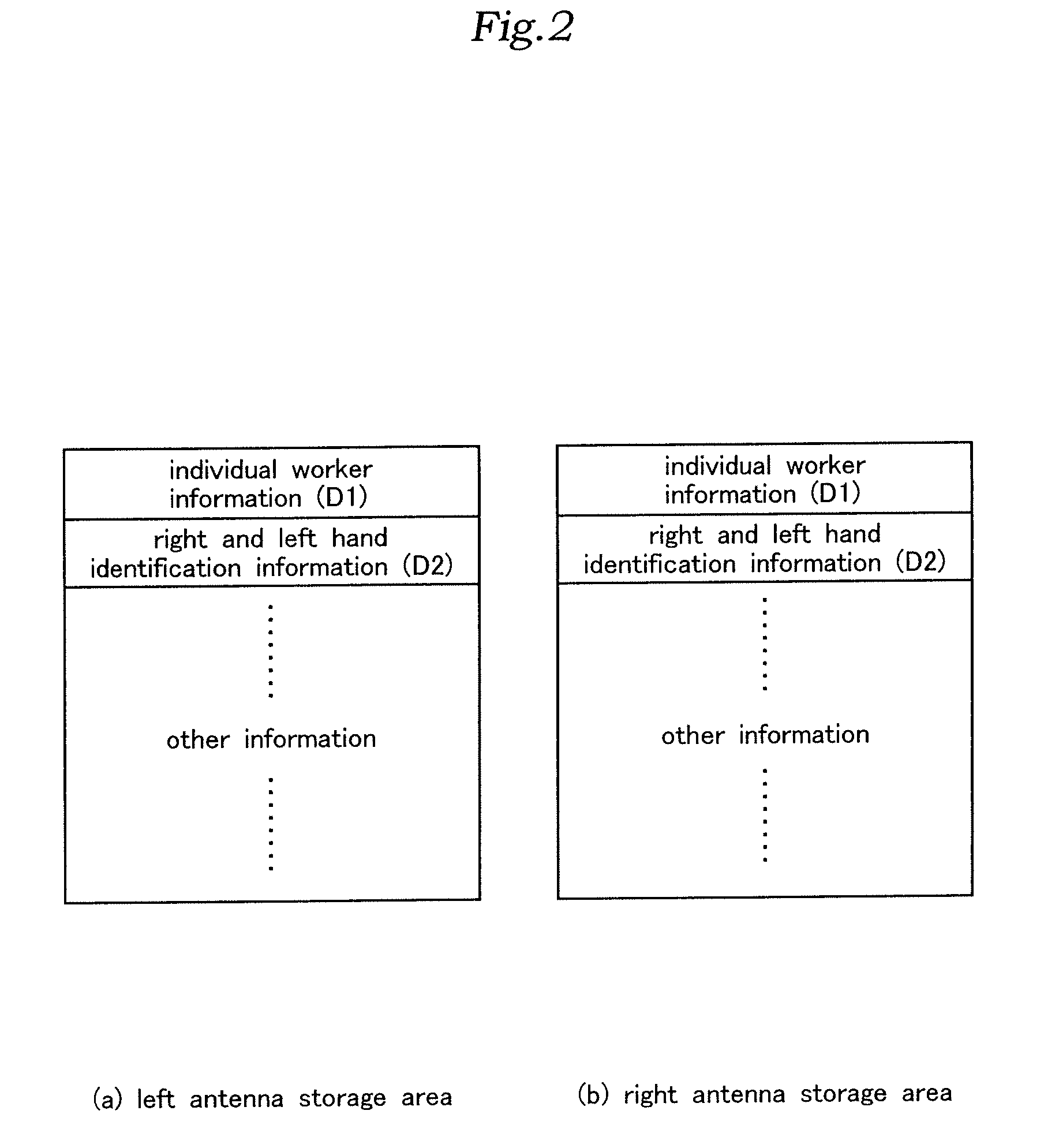
[0043]The main control unit 31 controls the overall system, and typically 10 comprises a microprocessor, ROM, RAM and peripheral support circuits. In this particular example, as illustrated in FIG. 2, the RAM is provided with a left antenna storage area (see FIG. 2a) for storing the reception information from the left hand RF antenna 2a and a right antenna storage area (see FIG. 2bfor storing the reception information from the right hand RF antenna 2b.

Problems solved by technology

However, because such a two-hand push button switch device uses push button switches that are each fitted with a strong return spring, the burden on the worker for each activation is so heavy that the worker suffers from excessive fatigue after repeating a large number of cycles of operation.
As a result, the worker is tempted to resort to improper modes of operation such as keeping one of the push buttons depressed by using adhesive tape so that the machine may be operated by using only one hand for depressing the other push button switch.
Also, because a conventional two-hand push button switch device can produce a normal output signal as long as the two push button switches are depressed simultaneously, it was not possible to exclude the possibility of improper or prankish modes of operation such as depressing the two push button switches by two workers each using only one hand, depressing one of the push button switches by using a long pole, and depressing the two push buttons by two hands but with the reversed hands of the worker facing away from the machine.
In such a conventional press fitted with a two-hand switch device, if a worker identification system or a worker logging system is introduced, it may be possible to identify the worker who is generally involved in the operation of the press (such as the one who initially powers up the press) from an ID obtained from an ID card of the like carried by each worker but it is difficult to identify the actual worker who is directly involved in the press work itself which may be considered as most hazardous.

Method used


Image

  • Two-hand switch device
  • Two-hand switch device
  • Two-hand switch device

Examples


Embodiment Construction

)

[0039]Preferred embodiments of the two-hand switch device of the present invention are described in the following in more detail with reference to the appended drawings.

[0040]FIG. 1 shows a hardware diagram of an exemplary two-hand switch device embodying the present invention. As shown in this drawing, the two-hand switch device 100 comprises a first RFID tag 1a configured to be worn on a pre-determined position (such as a wrist and finger) of a left hand (10a in FIG. 6) of a worker, a second RFID tag 1b configured to be worn on a pre-determined position (such as a wrist and finger) of a right hand (10b in FIG. 6) of the worker, a left hand RF antenna 2a placed in such a position as to enable a communication with the first RFID tag 1a worn on the pre-determined position of the left hand of the worker only when the left hand of the worker is placed in a pre-determined left hand safe position (13a in FIG. 6), a right hand RF antenna 2b placed in such a position as to enable a commun...


PUM


Abstract

Task—To provide a two-hand switch device that requires only a small load for each operation cycle.Means to Achieve the Task—The device comprises a left hand RF antenna placed in such a position as to enable a communication with the first RFID tag worn on the pre-determined position of the left hand of the worker only when the left hand of the worker is placed in a pre-determined left hand safe position, a right hand RF antenna placed in such a position as to enable a communication with the second RFID tag worn on the pre-determined position of the right hand of the worker only when the right hand of the worker is placed in a pre-determined right hand safe position and an output signal generating means for generating an output signal according to signals received by the left hand RF antenna and the right hand RF antenna.

Description

TECHNICAL FIELD[0001]The present invention relates to a two-hand switch device that can be operated only when both hands of a worker are placed in pre-determined safe positions so that a machine such as a press is prevented from activating when a hand of the worker is in a hazardous part.BACKGROUND OF THE INVENTION[0002]Conventionally known are two-hand switch devices that can be operated only when both hands of a worker are placed in pre-determined safe positions so that a machine such as a press is prevented from activating when a hand of the worker is placed in a hazardous part. See Patent Document #1, for instance.[0003]In the case of a press, a left hand safe position and a right hand safe position are designated some distance away from a work piece charge inlet of the press in a laterally spaced apart relationship. Each of the left and right hand safe positions is typically fitted with a push button switch having a relatively large button head. Only when both of the push butto...

Claims


Application Information

Patent Timeline
IPC IPC(8): F16P3/20G08B1/00
CPCF16P3/20B30B15/285
Inventor IIDA, TATSUYASHUTTO, MANABUFURUKAWA, HIROAKIKOSHI, TOSHIKITANAKA, TAKASHI
Owner ORMON CORP
Learn More