Vibration actuator

a linear actuator and actuator technology, applied in the direction of mechanical vibration separation, dynamo-electric machines, electrical apparatuses, etc., can solve the problems of inability to easily sense the vibration of the coin-type motor actually mounted and used in the apparatus, the limitation of the miniaturization of the cylindrical motor, and the inability to automate the mounting and mounting of the coin-type motor in the apparatus, so as to reduce the number of components, reduce the weight, and improve the effect of magnetic efficiency

Inactive Publication Date: 2009-06-11
NAMIKI PRECISION JEWEL CO LTD
View PDF7 Cites 17 Cited by
  • Summary
  • Abstract
  • Description
  • Claims
  • Application Information

AI Technical Summary

Benefits of technology

[0020]According to the invention disclosed in Claim 1, unlike the conventional vibration actuators where an elastic member supporting the moving part having a weight transfers vibration to the case, motion of the moving part having the two magnets is directly transferred as vibration through collision to the case, so that strong vibration can be instantaneously obtained in comparison with a vibration actuator using no collision. In addition, since the moving part includes the two magnets, the moving part has a sufficient weight without an additional component such as a weight, so that it is possible to reduce the number of components.
[0021]In addition, since the vibration actuator is formed in a flat shape, the vibration direction is perpendicular to the attached board, so that a user carrying a mobile communication apparatus such as a cellular phone can easily sense the vibration when the vibration actuator is actually built in the mobile communication actuator.
[0022]According to the invention disclosed in Claim 2, the plate-shaped magnetic member is disposed between the two magnets fastened, the magnetic flux of the magnets can be condensed in a portion facing the vibration direction, so that it is possible to improve the magnetic efficiency at the time of driving thereof.
[0023]According to the invention disclosed in Claim 3, the magnets are fastened by using the magnetic holder, so that it is possible to easily assemble the magnets in comparison with a case of using an adhesive.
[0024]According to the invention disclosed in Claim 4, the two coils are disposed in a direction where the magnetic fields thereof generated are repulsed each other at the time of applying an alternating current. There is no need for fixing the two magnets that are repulsed each other. In addition, it is possible to easily assemble the two magnets while maintaining the effect of vibration using collision.
[0025]According to the invention disclosed in Claim 5, the magnetic member is disposed in an outer side of the case, so that it is possible to prevent magnetic flux from being leaked from the coil(s) and to improve the magnetic efficiency of the magnetic circuit comprising the moving part and the coil(s).

Problems solved by technology

However, the cylindrical motor has a limitation to its miniaturization and a problem in its mounting automation.
However, in terms of its structure, since the coin-type motor is vibrated in a direction parallel to an attached board, there is a problem in that vibration of the coin-type motor actually mounted and used in an apparatus cannot be easily sensed.

Method used


Image

  • Vibration actuator
  • Vibration actuator
  • Vibration actuator

Examples


first embodiment

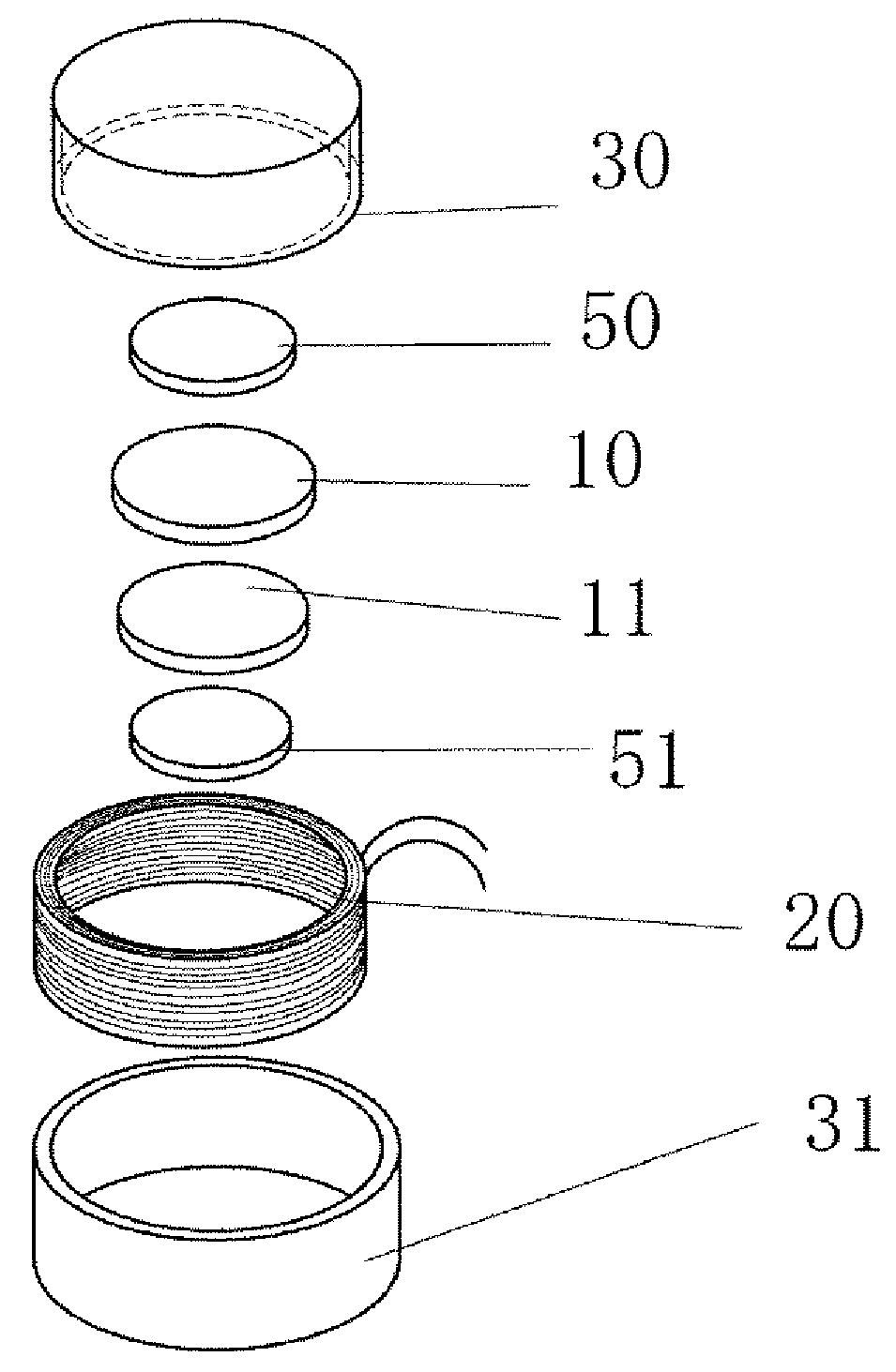
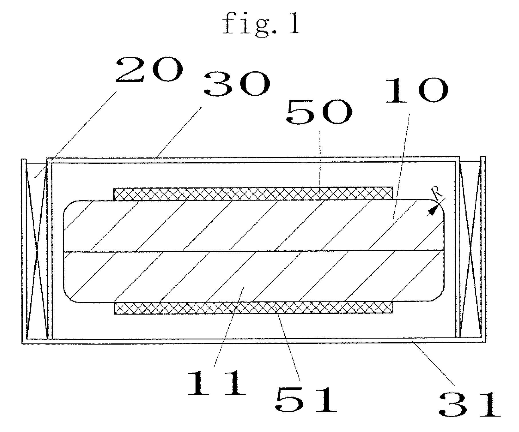
[0031]FIG. 1 is a cross-sectional view illustrating a vibration actuator according to a first embodiment of the present invention. The vibration actuator according to the embodiment includes a housing having covers 30 and 31, a moving part having magnets 10 and 11 and dampers 50 and 51, and a coil 20. FIG. 11 is a perspective view illustrating the vibration actuator according to the embodiment. Referring to FIG. 11, the vibration actuator has a circular planar shape. Alternatively, according to a mounting type, an elliptic shape, a circular shape, a polygonal shape, and the like can be selectively used as the planar shape.

[0032]In the vibration actuator according to the embodiment, the moving part is driven by applying an alternating current to the coil 20. Referring to FIG. 10, the magnets 10 and 11 are fastened in a direction where the magnetic poles are repulsed each other. Therefore, when the alternating current is applied to the coil 20, an attractive force and a repulsive forc...

second embodiment

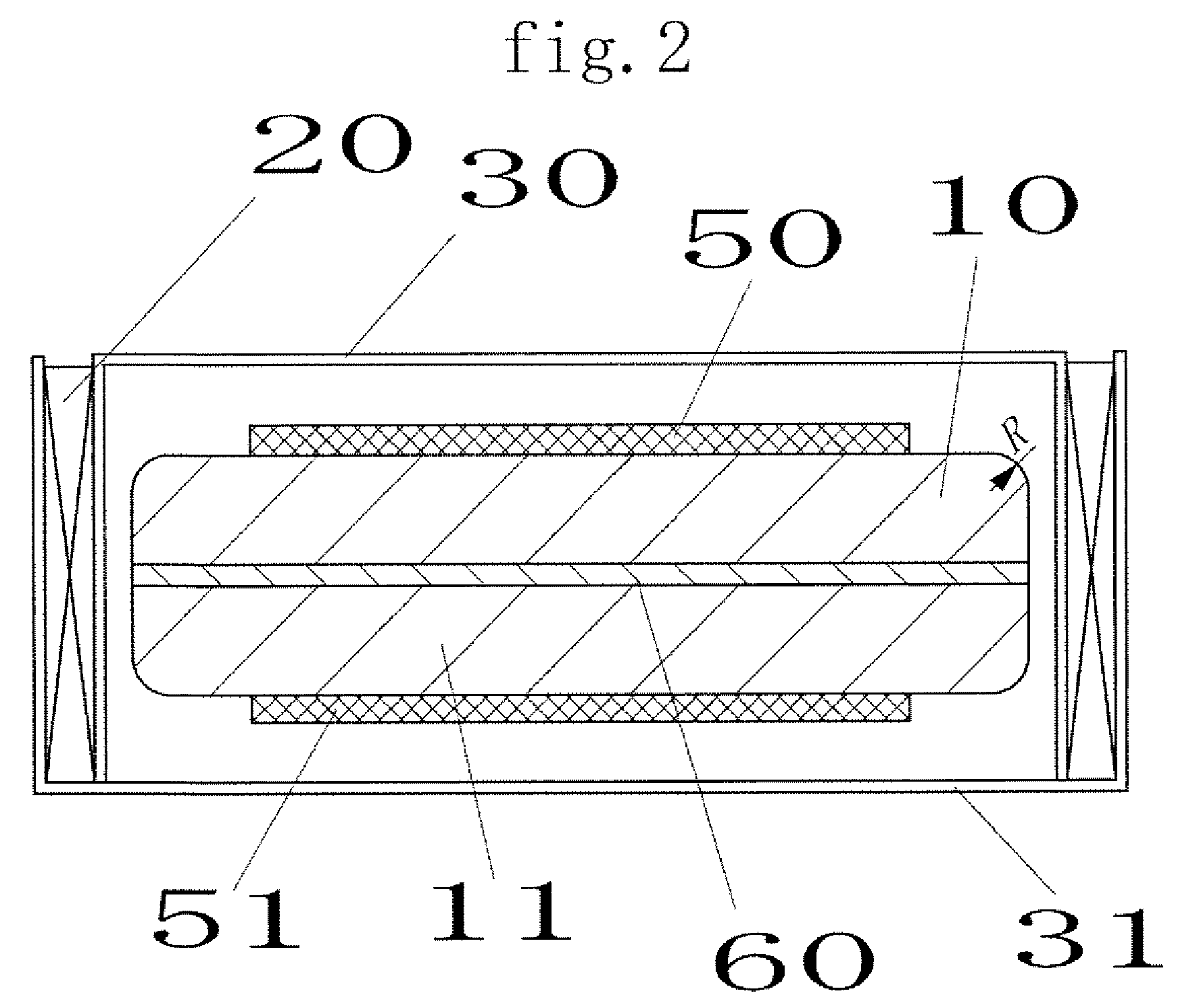
[0037]FIG. 4 is a cross-sectional view illustrating a vibration actuator according to a second embodiment of the present invention. The vibration actuator according to the embodiment includes a moving part including magnets 10 and 11, dampers 50 and 51, and a shaft bearing 80, a fixed part including a case 90, covers 32 and 33, and a coil 20, and a shaft 70 which penetrates through the moving part to be fastened to the covers.

[0038]In the embodiment, the shaft bearing 80 is provided to the moving part, and the shaft 70 penetrates through the shaft bearing 80 of the moving part to be fastened to the covers 32 and 33, so that a uniform gap between the coil 20 and the moving part is maintained. Accordingly, stable vibration can be obtained. In addition, since the uniform gap between the coil 20 and the moving part is maintained, an amount of air flow can be limited. Therefore, the air is used as a damper, so that a stable vibration can be obtained.

[0039]In addition, the corners of the ...

third embodiment

[0042]FIG. 7 is a cross-sectional view illustrating a vibration actuator according to a third embodiment of the present invention. In the vibration actuator according to the embodiment, a moving part includes a magnet 12 and dampers 50 and 51, and a fixed part includes covers 30 and 31 and coils 21 and 22. In the embodiment, the coils 21 and 22 not the magnet 12 are disposed in a direction where the magnetic fields generated from the coils 21 and 22 are repulsed each other when the alternating current is applied. Accordingly, the moving part can be vibrated similarly to the first embodiment.

[0043]In addition, in the embodiment, the corners of the magnet 12 are provided with a rounded portion R. Accordingly, during the vibration of the moving part, the moving part cannot be in contact with the wall surface of the cover 30 where the coils 20 and 21 are provided in a rear side thereof which is back to back the coils 21 and 22, so that the vibration of the moving part cannot be interfer...


PUM


Abstract

[Object] To provide a vibration actuator capable of obtaining sufficiently sensible vibration with a flat, thin shape maintained.
[Solving Means] Two magnets of a moving part are fixed in a direction where magnetic forces of the magnets are repulsed each other, and the moving part is disposed inside a coil of a fixed part in a housing, so that the moving part collides with the housing when an alternating current is applied to the coil. Therefore, vibration is transferred to the case through the collision. Accordingly, it is possible to implement a miniaturized vibration actuator capable of generating a sufficiently sensible vibration.

Description

TECHNICAL FIELD[0001]The present invention relates to a vibration linear actuator built in a mobile communication device such as a cellular phone and a portable liquid crystal game machine.[0002]Recently, in a mobile information device such as a cellular phone, a vibration generator is used for notifying a call signal or operating in tune with music. Conventionally, a cylindrical motor with an unbalance weight attached to a shaft thereof is used as an example of the vibration generator. However, the cylindrical motor has a limitation to its miniaturization and a problem in its mounting automation.[0003]In order to overcome the limitation and problem, a coin-type motor with a flat unbalanced weight attached to a shaft thereof has been proposed and practically used. However, in terms of its structure, since the coin-type motor is vibrated in a direction parallel to an attached board, there is a problem in that vibration of the coin-type motor actually mounted and used in an apparatus ...

Claims


Application Information

Patent Timeline
Patent Type & Authority Applications(United States)
IPC IPC(8): H02K33/18H02K33/12
CPCB06B1/045
Inventor AOYAGI, TOMOHIDESUZUKI, TOSHIO
Owner NAMIKI PRECISION JEWEL CO LTD
Why Eureka
Try Eureka