Light Emitting Diode (LED) Driving Device

a technology of driving device and light emitting diode, which is applied in the direction of electric variable regulation, process and machine control, instruments, etc., can solve the problems of increasing cost, occupying space, and complicated circuit design, and achieves a much simpler control circuit and control manner. , the effect of reducing cos

Inactive Publication Date: 2009-06-11
LEADTREND TECH
View PDF5 Cites 43 Cited by
  • Summary
  • Abstract
  • Description
  • Claims
  • Application Information

AI Technical Summary

Benefits of technology

[0011]It is one of the objectives of the claimed invention to provide an LED driving device to solve the problems of complicated circuit design and high cost existing in the prior art.
[0018]The LED driving device disclosed in the present invention utilizes the primary-side current of the transformer to control feedback, and thus linear voltage regulators and light couplers are not needed to isolate the primary-side from the secondary-side of the transformer to prevent danger of an electric shock when changing output LEDs, which can reduce cost. In addition, the LED driving device disclosed in the present invention adjusts the output current (i.e., the secondary-side current of the transformer) through adjusting the value of the resistor in the feedback circuit, for example, adjusting the resistance of the resistor Rcs, to control the brightness of the LED modules. Compared with the prior art, the control manner is much simpler. Furthermore, the LED driving device disclosed in the present invention is suitable for high output power applications (for example, >200 W). Within the LED driving device disclosed in the present invention, only a single controller with feedback function (i.e., the PFC) is used and its control circuit is much simpler and the whole cost is cheaper.

Problems solved by technology

In addition, in high power output (greater than 150 W) applications, a transformer of large-scale is necessary, which results in increasing cost, occupying space, and accompanying complicated thermal dissipation problems.
Not only circuit designs become more complicated, but also cost becomes more expensive.

Method used


Image

  • Light Emitting Diode (LED) Driving Device
  • Light Emitting Diode (LED) Driving Device
  • Light Emitting Diode (LED) Driving Device

Examples


Embodiment Construction

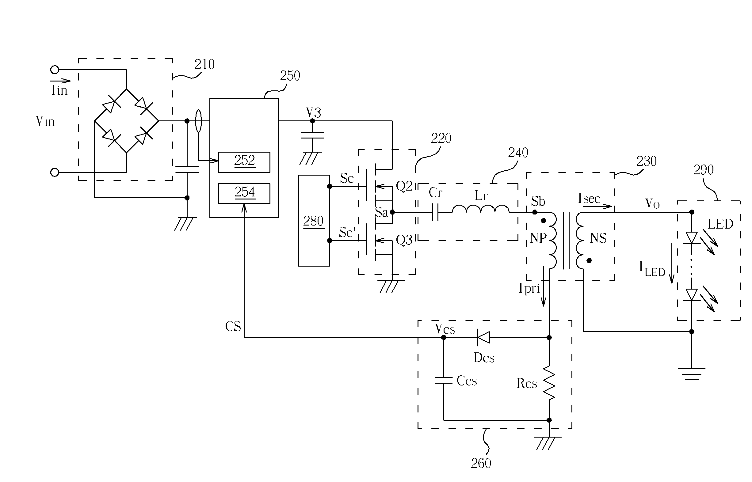
[0025]Please refer to FIG. 3. FIG. 3 is a diagram of an LED driving device according to an embodiment of the present invention. The LED driving device includes a bridge switch circuit 220, a transformer 230, a resonant circuit 240, a power factor correction (PFC) circuit 250, and a feedback circuit 260.

[0026]The PFC circuit 250 is coupled between a bridge rectifier circuit 210 and the bridge switch circuit 220. The resonant circuit 240 is coupled between the bridge switch circuit 220 and a first end of the primary-side of the transformer 230. The feedback circuit 260 is coupled between a second end of the primary-side of the transformer 230 and a voltage feedback end of the PFC circuit 250.

[0027]The input voltage Vin is rectified by the bridge rectifier circuit 210 and then inputted to the PFC circuit 250. The PFC circuit 250 includes two feedback paths. A current feedback path 252 is connected to the bridge switch circuit 220 to make the waveform of the input current Iin follow the...


PUM


Abstract

A light emitting diode (LED) driving device includes a power factor correction (PFC) circuit, a bridge switch circuit, a resonant circuit, a transformer and a feedback circuit. The PFC circuit adjusts an output signal thereof based on a feedback signal. The bridge switch circuit transforms the output signal of the PFC circuit into a pulse signal. The resonant circuit resonates and outputs a sinusoidal signal to a primary-side of the transformer based on the pulse signal. The feedback circuit outputs the feedback signal to the PFC circuit in response to a primary-side current of the transformer. Therefore, an output current of the LED driving device is adjusted through modulating the feedback circuit.

Description

BACKGROUND OF THE INVENTION[0001]1. Field of the Invention[0002]The present invention relates to a light emitting diode (LED) driving device, and more particularly, to an LED driving device suitable for high power output to drive at least one LED module.[0003]2. Description of the Prior Art[0004]Light emitting diodes (LED) are light emitting elements manufactured of semiconductor materials. Unlike the conventional lighting, the LED belongs to cold lighting and has plenty of advantages, such as high brightness, high lighting efficiency, uncomplicated driving circuits, low power consumption, and fast response. The LED has gradually replaced the conventional lighting.[0005]Circuit designs of the LED driving device usually adopt a design for isolating the primary-side from the secondary-side of a transformer for safety considerations. Please refer to FIG. 1. An input voltage Vin is rectified by a bridge rectifier circuit 110 to generate a primary-side voltage V1. Herein the primary-side...

Claims


Application Information

Patent Timeline
Patent Type & Authority Applications(United States)
IPC IPC(8): H05B41/24
CPCY02B20/348H05B33/0815H05B45/355Y02B20/30H05B45/392H05B45/382H05B45/39
Inventor CHU, YI-SHANCHAO, HSING-KUO
Owner LEADTREND TECH
Why Eureka
Try Eureka