Printer and control method thereof

a control method and printer technology, applied in the field of inkjet printers, can solve the problems of difficult to increase the electric power to be supplied to the heater, take a longer time before the inkjet printer starts its printing operation, and increase the cost of the inkjet printer, etc., and achieve the effect of increasing costs

Active Publication Date: 2009-06-11
RISO KAGAKU CORP
View PDF3 Cites 4 Cited by
  • Summary
  • Abstract
  • Description
  • Claims
  • Application Information

AI Technical Summary

Benefits of technology

[0027]According to the foregoing configurations, the inkjet printer designed to heat the ink up to the predetermined temperature is capable of starting its printing operation within a shorter time without entailing the increased costs. The foregoing configuration is particularly effective to the printer of an ink-circulation type which circulates the ink.

Problems solved by technology

However, the inclusion of the power supply unit with the large capacity in the inkjet printer causes increase in costs.
Otherwise, the small capacity forces the power supply unit to supply the heater with an electric power controlled with consideration given to a maximum amount of electric power needed for the printing operation, and thus makes it difficult to increase the electric power to be supplied to the heater.
As a result, it takes a longer time before the inkjet printer starts its printing operation.

Method used


Image

  • Printer and control method thereof
  • Printer and control method thereof
  • Printer and control method thereof

Examples


first example

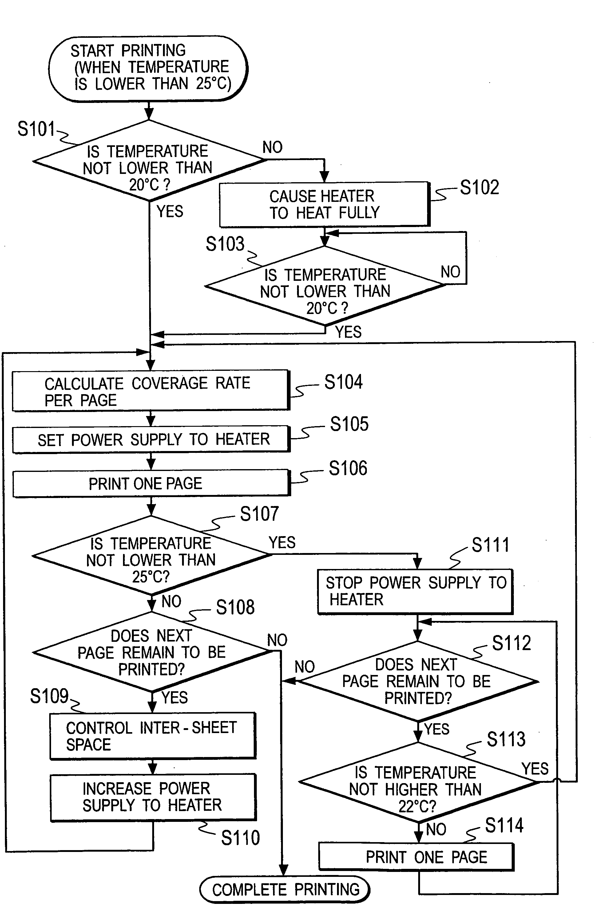
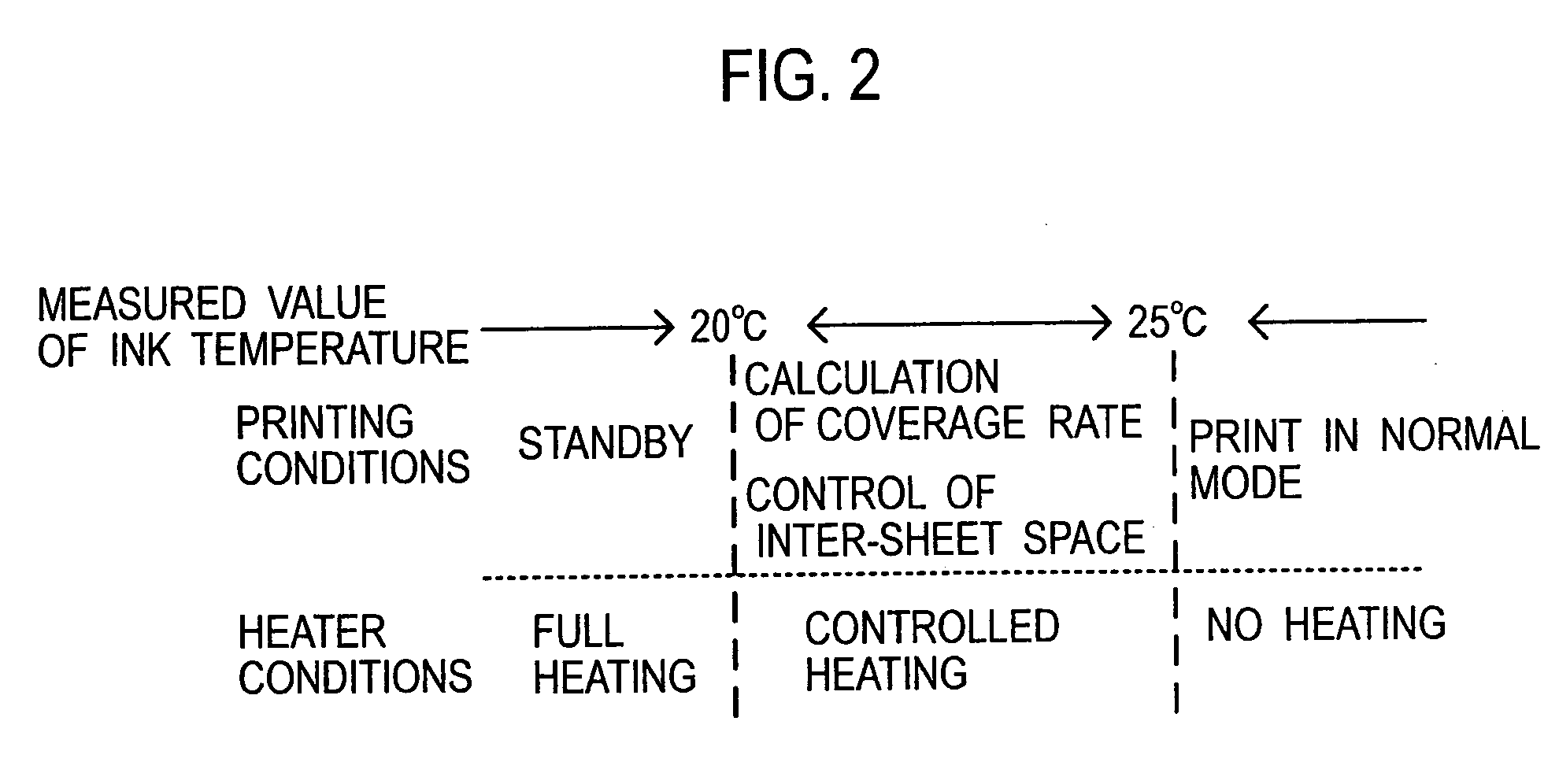
[0047]Descriptions will be provided for the first example. FIG. 2 shows a relationship among a measured value of the ink temperature (shown in the uppermost row in FIG. 2), a printing condition (the middle row in FIG. 2) and an operating condition of the heater 170 (the lowermost row in FIG. 2). In the first example, as shown in FIG. 2, when the measured value of the ink temperature is lower than 20° C., the inkjet printer enters standby mode without carrying out any actual printing operation, and the heater 170 heats the ink with a maximum amount of electric power which can be supplied to the heater 170 (in full heating mode) by the power supply unit. At this time, the ink is circulated in the circulation passage CR. This makes it possible to increase the ink temperature rise rate, and accordingly to shorten the time for which the inkjet printer stands by for starting the printing operation as much as possible. It goes without saying that the maximum amount of electric power which ...

second example

[0059]Next, descriptions will be provided for the second example. FIG. 5 shows a relationship among a measured value of the ink temperature (shown in the uppermost row in FIG. 5), a printing condition (the middle row in FIG. 5) and an operating condition of the heater 170 (the lowermost row in FIG. 5). In the second example, as shown in FIG. 5, when the measured value of the ink temperature is lower than 20° C., the inkjet printer is put in standby mode without carrying out any actual printing operation, and the heater 170 heats the ink with a maximum amount of electric power which can be supplied to the heater 170 by the power supply unit, like in the first example. At this time, the ink is circulated in the circulation passage CR. This makes it possible to increase the ink temperature rise rate, and accordingly to shorten the time for which the inkjet printer stands by for starting the printing operation as much as possible. It goes without saying that the maximum amount of electr...


PUM


Abstract

An inkjet printer includes an inkjet head configured to perform printing on a printing sheet by use of ink. The inkjet printer includes: a heater configured to heat the ink; a thermometer configured to measure the temperature of the ink; and a controller configured to control the amount of electric power to be supplied to the heater and to control the inkjet head. In a case where the measured value of the ink temperature measured by the thermometer is in a range of a first reference temperature inclusive to a second reference temperature exclusive, the controller calculates a coverage rate of a page to be printed, and accordingly changes the amount of electric power to be supplied to the heater depending on the coverage rate thus calculated.

Description

CROSS REFERENCE TO RELATED APPLICATION[0001]This application is based upon and claims the benefit of priority from the prior Japanese Patent Application No. 2007-316026, filed on Dec. 6, 2007, the entire contents of which are incorporated herein by reference.BACKGROUND OF THE INVENTION[0002]1. Field of the Invention[0003]The present invention relates to an inkjet printer and a control method thereof, and particularly to an ink temperature controlling mechanism and an ink temperature controlling method of the inkjet printer.[0004]2. Description of the Related Art[0005]As described in Japanese Unexamined Patent Publication No. 2004-276486, a temperature range for guaranteeing the ink performance is specified for an inkjet printer for the purpose of obtaining a better printing result. Therefore, there have been practically-used inkjet printers each including a heater for heating ink, and thus causes the heater to heat the ink when a lower ambient temperature makes the ink temperature l...

Claims


Application Information

Patent Timeline
Patent Type & Authority Applications(United States)
IPC IPC(8): B41J29/38
CPCB41J2/17509B41J29/377B41J2/195
Inventor OKADA, YOSHIYUKINISHIMURA, ASAYO
Owner RISO KAGAKU CORP
Why Eureka
Try Eureka