
Transformation-optical design of reconfigurable optical devices

Active Publication Date: 2009-06-11
DUKE UNIV
View PDF9 Cites 4 Cited by
  • Summary
  • Abstract
  • Description
  • Claims
  • Application Information

AI Technical Summary

Benefits of technology

[0003]Metamaterials offer an enormous degree of freedom for manipulating electromagnetic fields, as independent and nearly arbitrary gradients can be introduced in the components of the effective permittivity and permeability tensors. In order to exploit such a high degree of freedom, a viable method for the well-aimed design of complex materials would be desirable.
[0006]It would be desirable to have also a tool for the design of electromagnetic / optical components that takes advantage of the high degree of design freedom provided by the transformation-optical approach, but allows the transfer of field manipulations outside the transformation-optical material. Such a method would allow the creation of optical devices with unconventional electromagnetic / optical behavior and functionality that exceeds the abilities of conventional components like lenses, beam steerers, beam shifters, beam splitters and similar.

Problems solved by technology

However, for the sake of the continuity of the transformation, the field manipulation cannot be transferred to another medium or free space and thus remains an, in many cases, undesired local phenomenon.

Method used


Image

  • Transformation-optical design of reconfigurable optical devices
  • Transformation-optical design of reconfigurable optical devices
  • Transformation-optical design of reconfigurable optical devices

Examples


Embodiment Construction

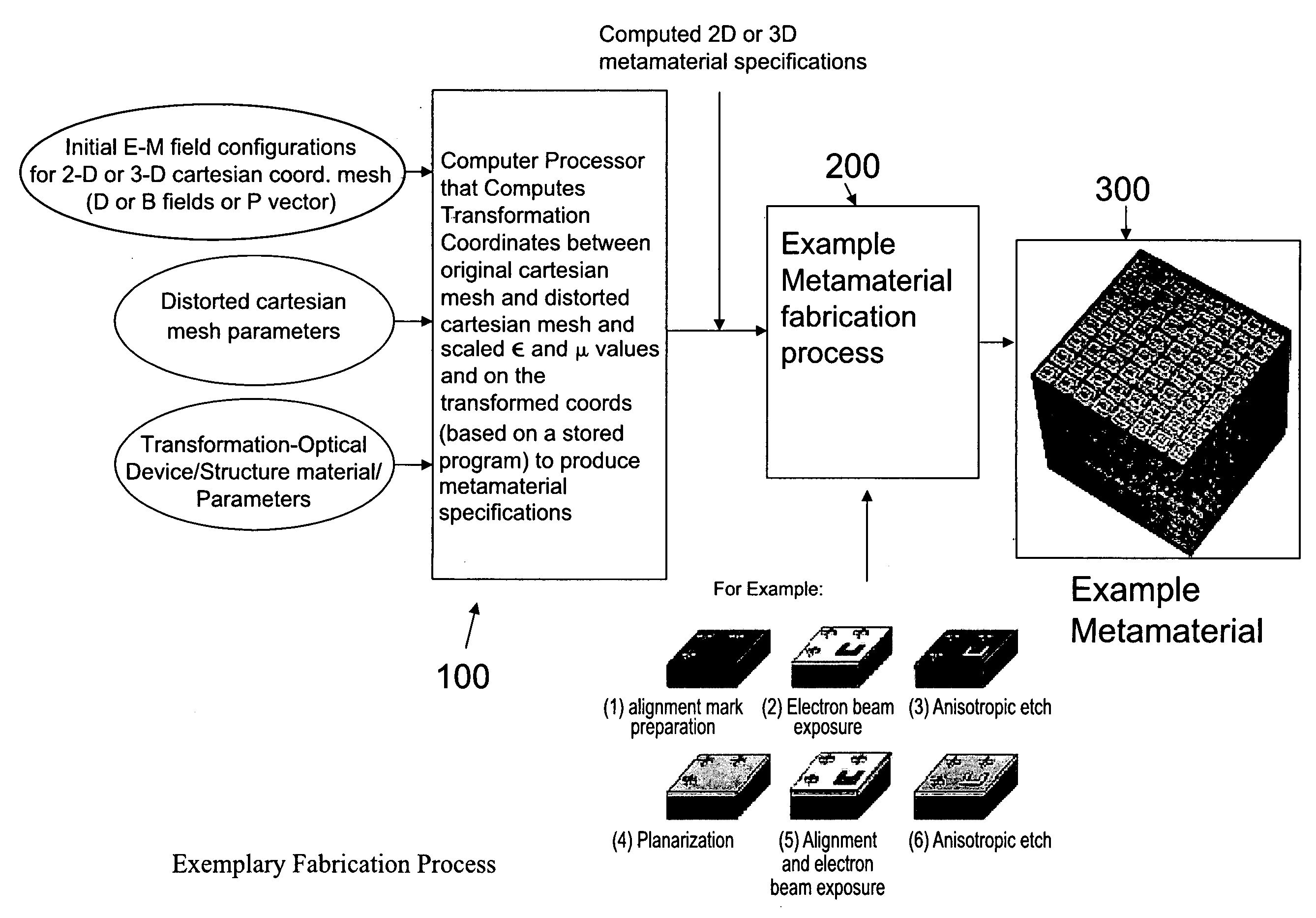
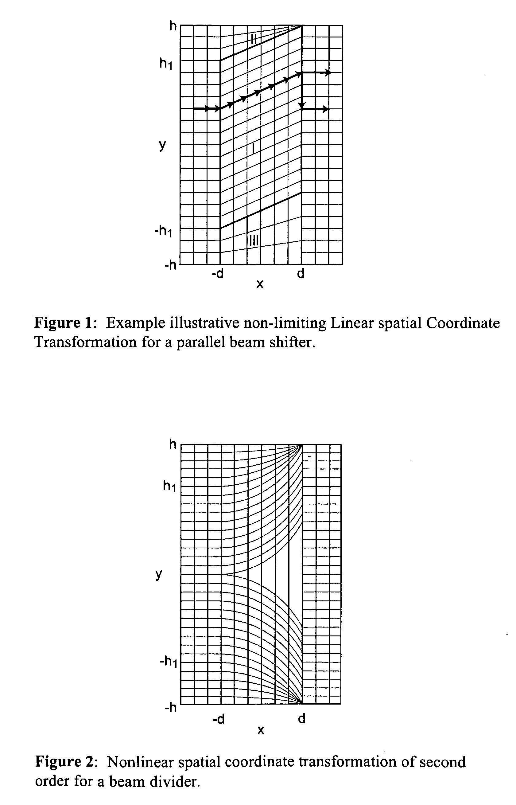
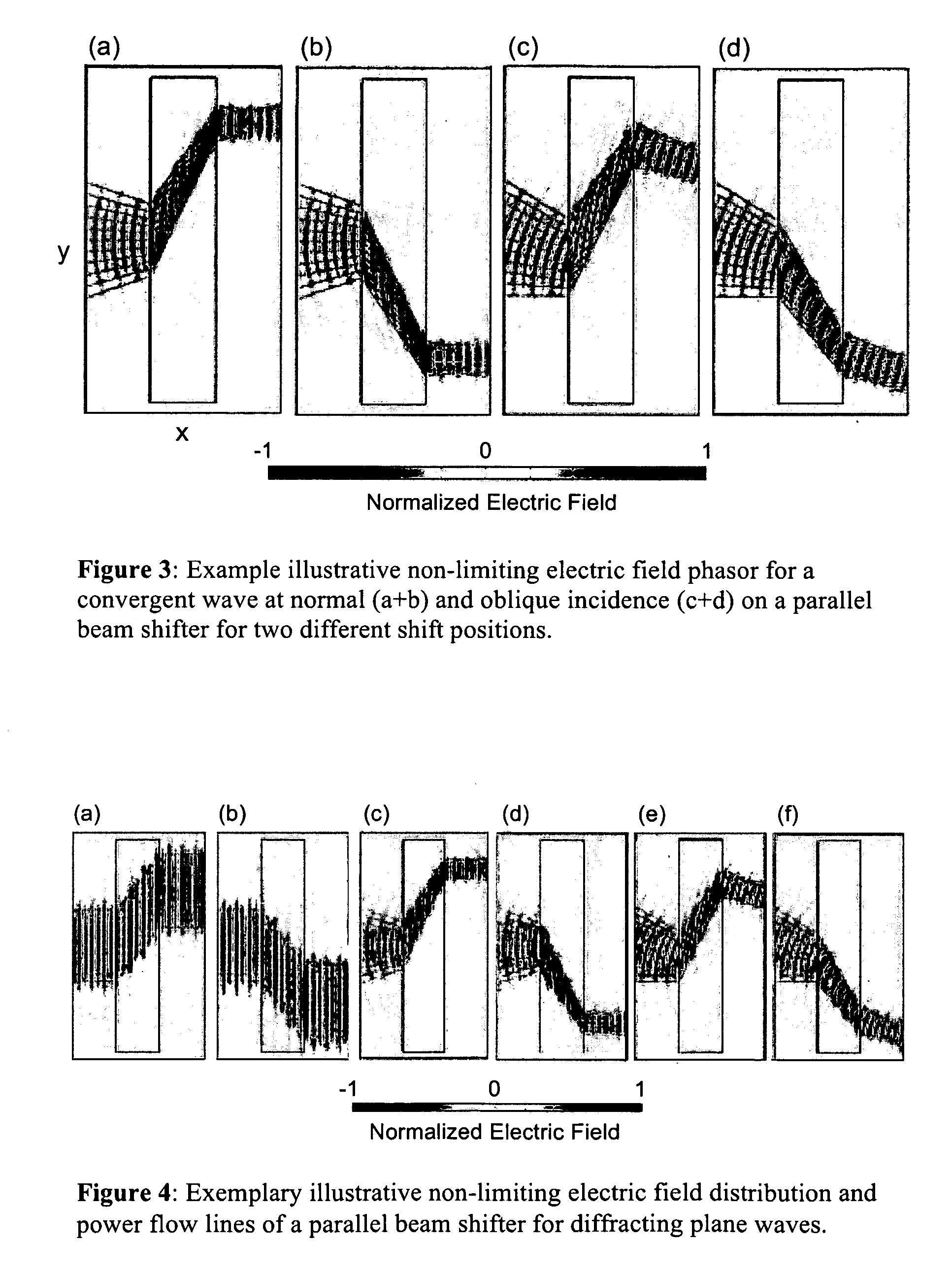
[0019]The exemplary illustrative non-limiting technology herein provides a generalized approach to the method of form-invariant coordinate transformations of Maxwell's equations based on finite embedded coordinate transformations. The use of embedded transformations adds a significant amount of flexibility to the transformation design of complex materials. For example, with finite-embedded transformations, it is possible to transfer field manipulations from the transformation-optical medium to a second medium, eliminating the requirement that the transformation optical structure be invisible to an external observer. The finite-embedded transformation thus significantly broadens the range of materials that can be designed to include device-type structures capable of focusing or steering electromagnetic waves. Like transformation optical devices, the finite-embedded transform structures can be reflectionless under conditions that we describe below. The general methodology is graphical...


PUM


Abstract

The design method for complex electromagnetic materials is expanded from form-invariant coordinate transformations of Maxwell's equations to finite embedded coordinate transformations. Embedded transformations allow the transfer of electromagnetic field manipulations from the transformation-optical medium to another medium, thereby allowing the design of structures that are not exclusively invisible. A topological criterion for the reflectionless design of complex media is also disclosed and is illustrated in conjunction with the topological criterion to design a parallel beam shifter and a beam splitter with unconventional electromagnetic behavior.

Description

CROSS-REFERENCES TO RELATED APPLICATIONS[0001]This application claims the benefit of priority from provisional application No. 60 / 987,014 filed Nov. 9, 2007, and from provisional application No. 60 / 987,127 filed Nov. 12, 2007, the contents of which are incorporated herein by reference.FIELD[0002]The technology herein relates to optical phenomena, and more particularly to complex electromagnetic materials that allow the transfer of electromagnetic field manipulations from the transformation-optical medium to another medium. The technology herein also relates to parallel beam shifters and beam splitters with unconventional electromagnetic behavior.BACKGROUND AND SUMMARY[0003]Metamaterials offer an enormous degree of freedom for manipulating electromagnetic fields, as independent and nearly arbitrary gradients can be introduced in the components of the effective permittivity and permeability tensors. In order to exploit such a high degree of freedom, a viable method for the well-aimed ...

Claims


Application Information

Patent Timeline
IPC IPC(8): G02F1/01G02B5/22G06G7/58G06F19/00
CPCG02F1/01G02F2202/30G06F17/5018G02B27/1073G05B19/4097G02B1/002G06F30/23
Inventor RAHM, MARCOSMITH, DAVID R.SCHURIG, DAVID A.
Owner DUKE UNIV
Learn More