
Power closing latch device

Inactive Publication Date: 2009-06-18
VOLVO CAR CORP
View PDF6 Cites 26 Cited by
  • Summary
  • Abstract
  • Description
  • Claims
  • Application Information

AI Technical Summary

Benefits of technology

[0002]In newly produced vehicles it is an aim to attain an interior passenger compartment, which is as quiet as possible. One measure that is taken to achieve this is to attain high sealing forces between doors or lids and the body of the vehicle is to reduce and mitigate disturbing noise from the outside environment to penetrate into the passenger compartment of the vehicle. To be able to close the door or lid, the sealing forces must be overcome, and this is possible with an automatic closing device.
[0011]It is further desirable to provide a power closing latch device that will require minor adjustments at assembly in the factory and that will not take up a great deal of space and that is inexpensive to manufacture.

Problems solved by technology

One drawback with the high sealing forces exerted by, for example, sealing strips is that it is hard to overcome the sealing forces to close the door or lid to a fully closed position by hand as the pawl just reaches the safety position.
When the sealing strips gradually lose their rigid properties due to age or being in a cold environment, the sealing strips exert lower forces that push the door or lid outwards.
When this occurs, the spring force acting on the claw becomes too high and this leads to larger tolerances and the claw moves past the safety recess too fast to trigger the sensor device.
As a result, the electric motor will not receive a signal to rotate the claw so that the pawl can mesh with the lock recess, and thus the pawl never reaches the lock recess.
Prior art power closing latch devices are configured to use an additional switch which senses when the pawl is in the undefined position, but to implement an extra switch will result in several drawbacks.
An additional switch will occupy more space within the device, which will make the device larger which is not desirable due to already high demands on less bulky parts.
An additional switch will also lead to more expensive electronics and cables must be installed.
Thus, the more electronics that are used the harder it is to attain a long operating time during the whole lifetime of the vehicle.

Method used


Image

  • Power closing latch device
  • Power closing latch device
  • Power closing latch device

Examples


Embodiment Construction

[0030]In the description below various directions are given such as front, rear, side, up and down. These directions are given with reference to a vehicle driving in a forward direction and to the orientation of the particular embodiment shown in the figures. The power closing device according to the invention can be oriented in different ways, and one possible orientation is shown in FIG. 2. The striker can be fixed on the vehicle or on a pivoting part of the vehicle and vice versa to the rest of the power closing device according to the invention.

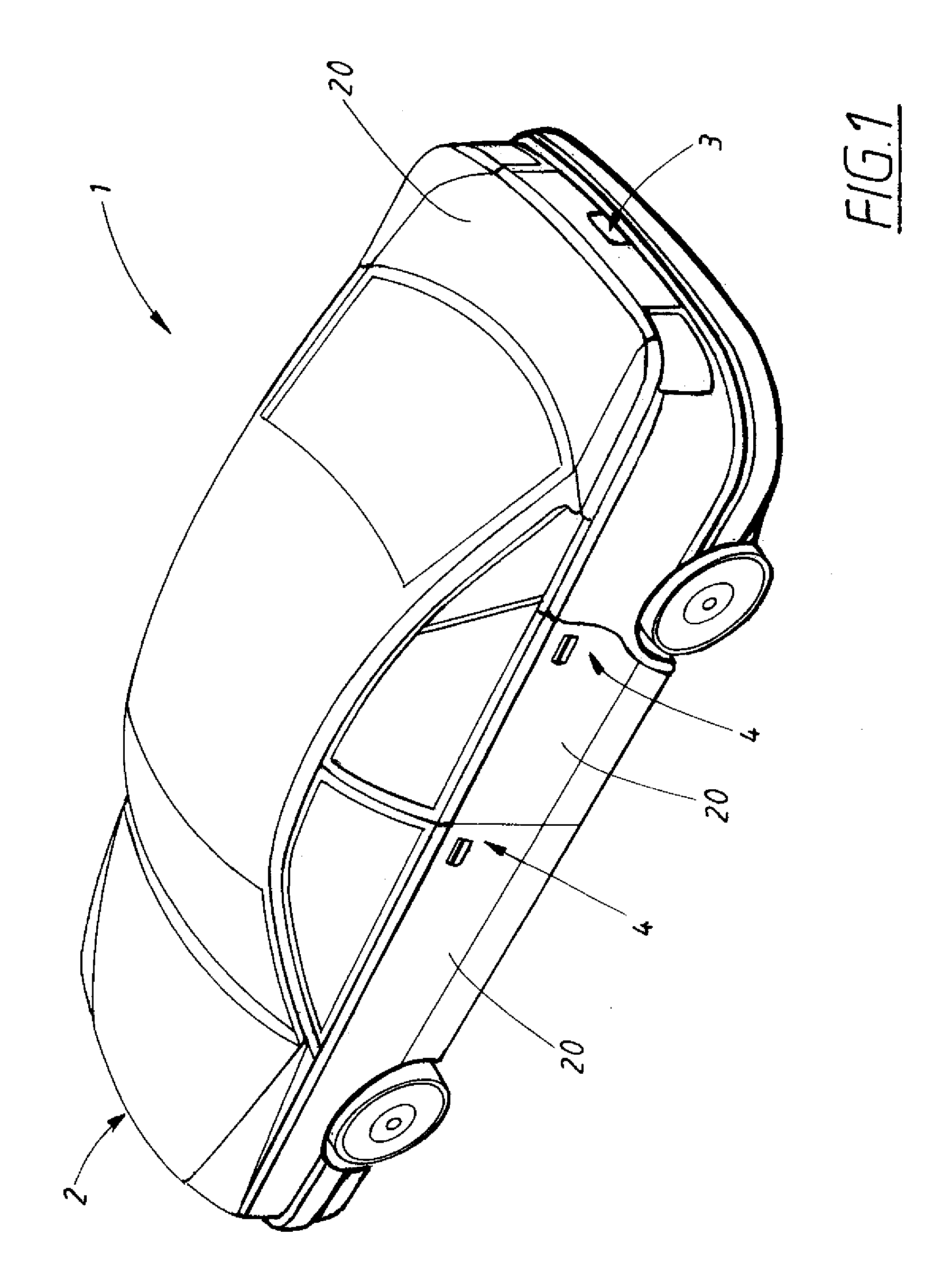
[0031]FIG. 1 shows a schematic isometric view of a vehicle 1 with a front 2, a rear 3 and sides 4. The doors, the bonnet, the boot lid, luggage boot or other lids can be provided with an automatic closing device in the form of the power closing latch device 5 according to one embodiment of the invention.

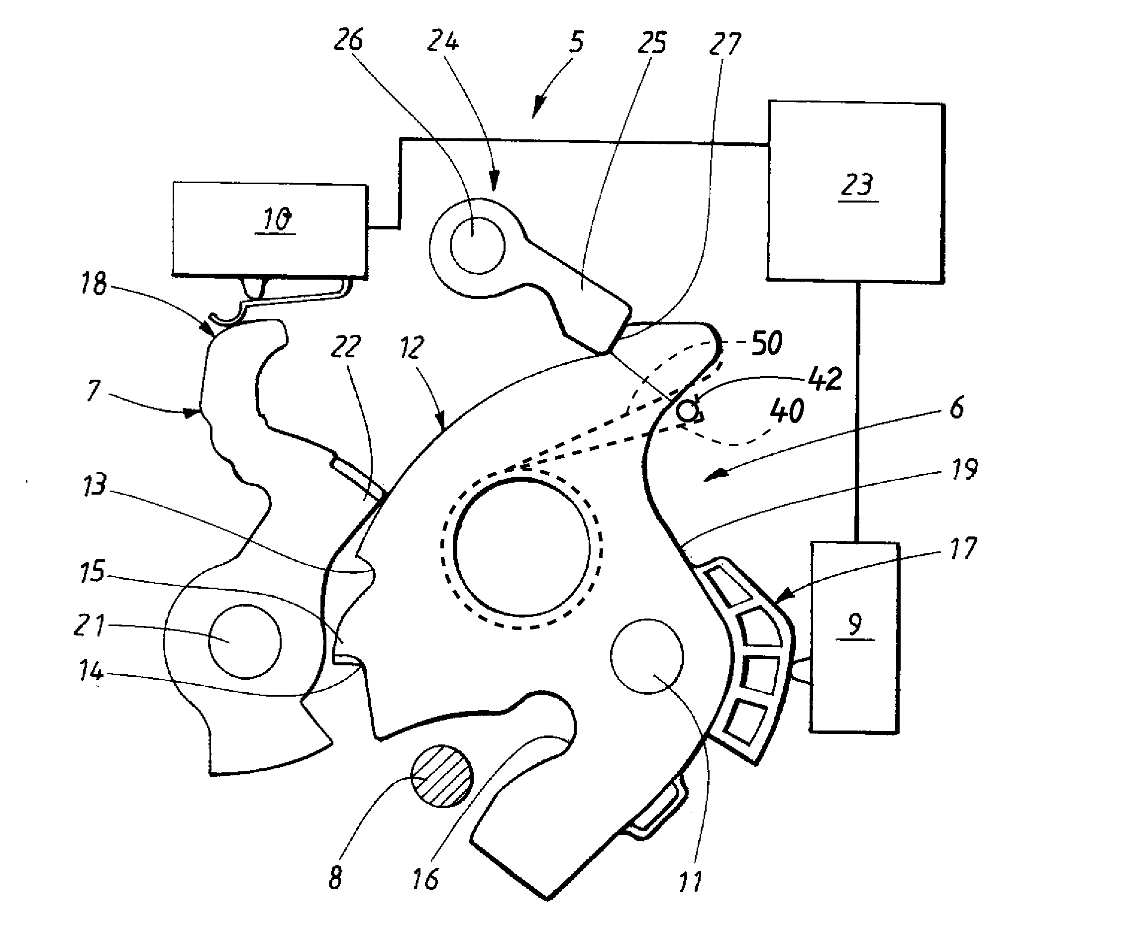
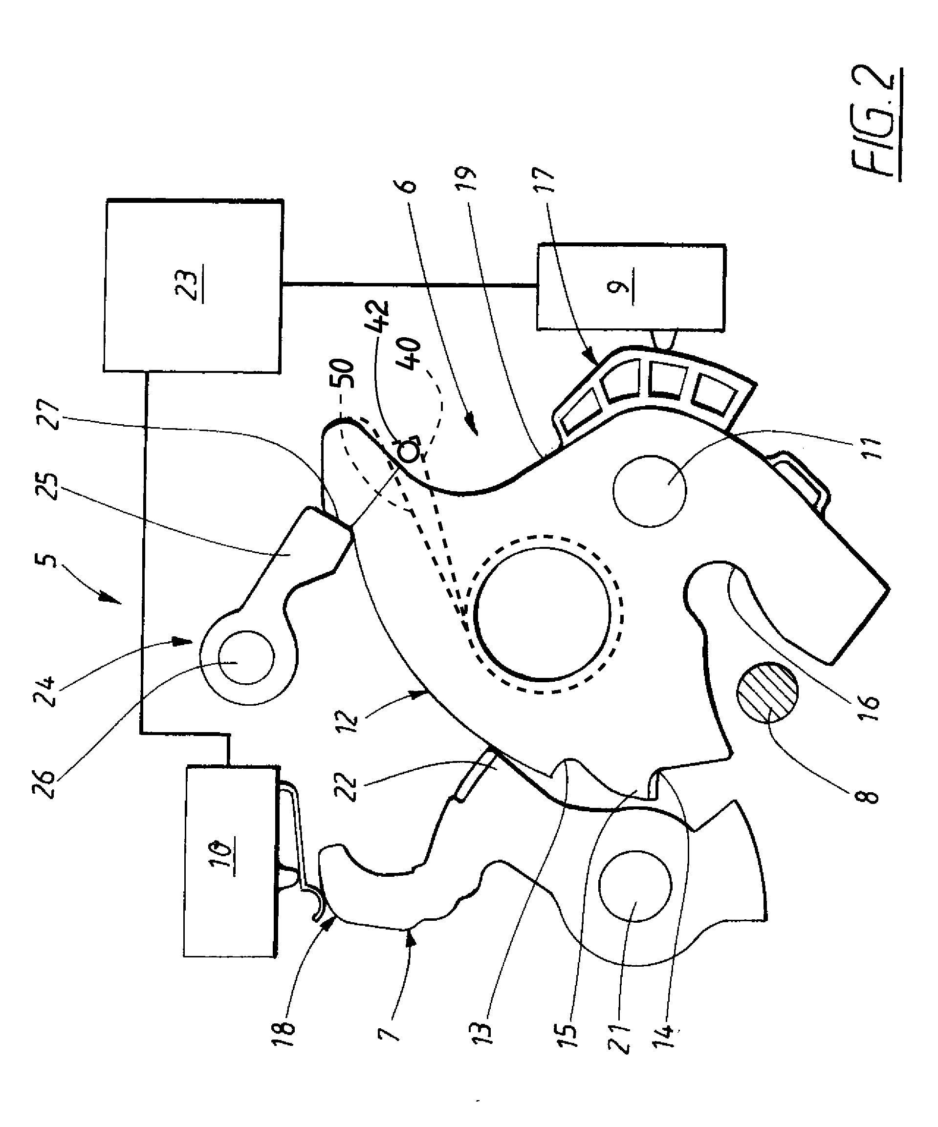
[0032]FIG. 2 shows a view of a power closing latch device 5 in an open position. The view shows a claw 6, a pawl 7, a striker 8 and first...


PUM


Abstract

A power closing latch device for a door or lid in a vehicle, which device comprises a claw, a pawl and a striker. The pawl meshes with a safety recess and a lock recess of the claw in a safety position and a locked position. The striker is provided in a groove and rotates together with the claw, at closing of the door or lid. A spring is provided acting on the claw, which spring keeps the claw in the safety position, when the door or lid is partially closed. An electric motor rotates the claw between the safety position and the closed position. An additional spring acting on the claw, which additional spring exert a counterforce on the claw to prevent the claw to stop in an undefined position, between the safety position and the closed position during a power closing process. A method for power closing of a door or lid of a vehicle is also provided.

Description

FIELD OF THE INVENTION[0001]The present invention relates generally to a power closing latch device for a door or lid in a vehicle and a method for power closing of a door or lid in a vehicle.BACKGROUND OF THE INVENTION[0002]In newly produced vehicles it is an aim to attain an interior passenger compartment, which is as quiet as possible. One measure that is taken to achieve this is to attain high sealing forces between doors or lids and the body of the vehicle is to reduce and mitigate disturbing noise from the outside environment to penetrate into the passenger compartment of the vehicle. To be able to close the door or lid, the sealing forces must be overcome, and this is possible with an automatic closing device.[0003]In the door or lid and the vehicle body a power closing latch device according to prior art is provided. The power closing latch device comprises a claw, a pawl and a striker cooperating with the claw. The claw has a safety recess and a lock recess and is rotatable...

Claims


Application Information

Patent Timeline
IPC IPC(8): E05B65/12
CPCE05B17/0037E05B81/20E05B81/68E05B81/66E05B77/34Y10T292/08
Inventor DOMINIQUE, CHRISTER GUSTAV
Owner VOLVO CAR CORP
Learn More