This helps you quickly interpret patents by identifying the three key elements:
Problems solved by technology
Method used
Benefits of technology
Benefits of technology
[0018]Therefore, the thermal expansion amount of the bearing housing as a result of operating the variable displacement type exhaust turbo supercharger is smaller than the thermal expansion amount of the turbine housing and the bolt. Accordingly, while operating the variable displacement type exhaust turbo supercharger, the fastening force of the bolt for fastening the turbine housing and the bearing housing decreases, and the contact pressure of the gasket decreases.
[0087]According to the present invention, an exhaust turbo supercharger that is able to effectively prevent exhaust gas that has flowed into between the turbine housing and the bearing housing from leaking to outside of the device, while allowing an excellent level of workability in assembly and disassembly, can be provided.
Problems solved by technology
Moreover, since the thread face of the bolt that engages with the screw hole of the turbine housing is in surface contact with the turbine housing, the temperature of this bolt becomes high.
Method used
Image
Click on the blue label to locate the original text in one second.
Reading with bidirectional positioning of images and text.
Examples
first embodiment
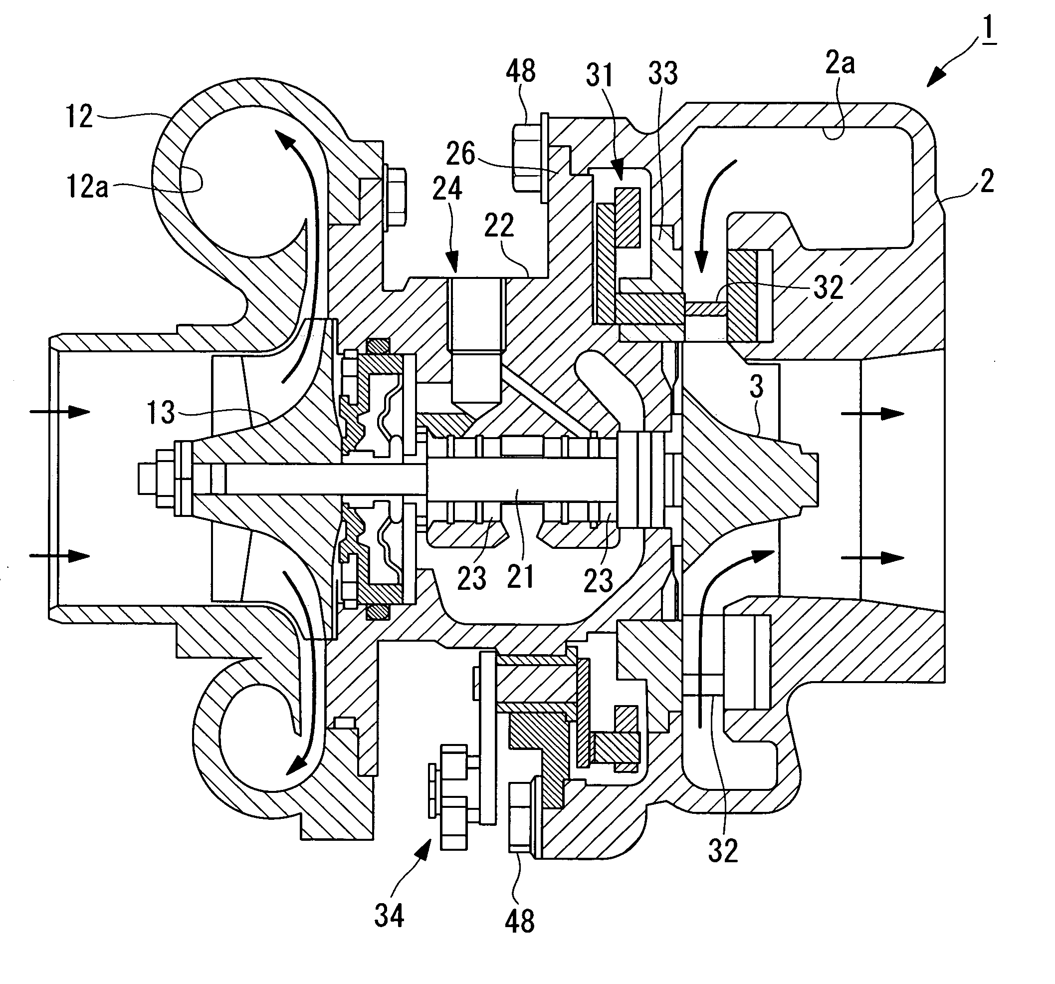
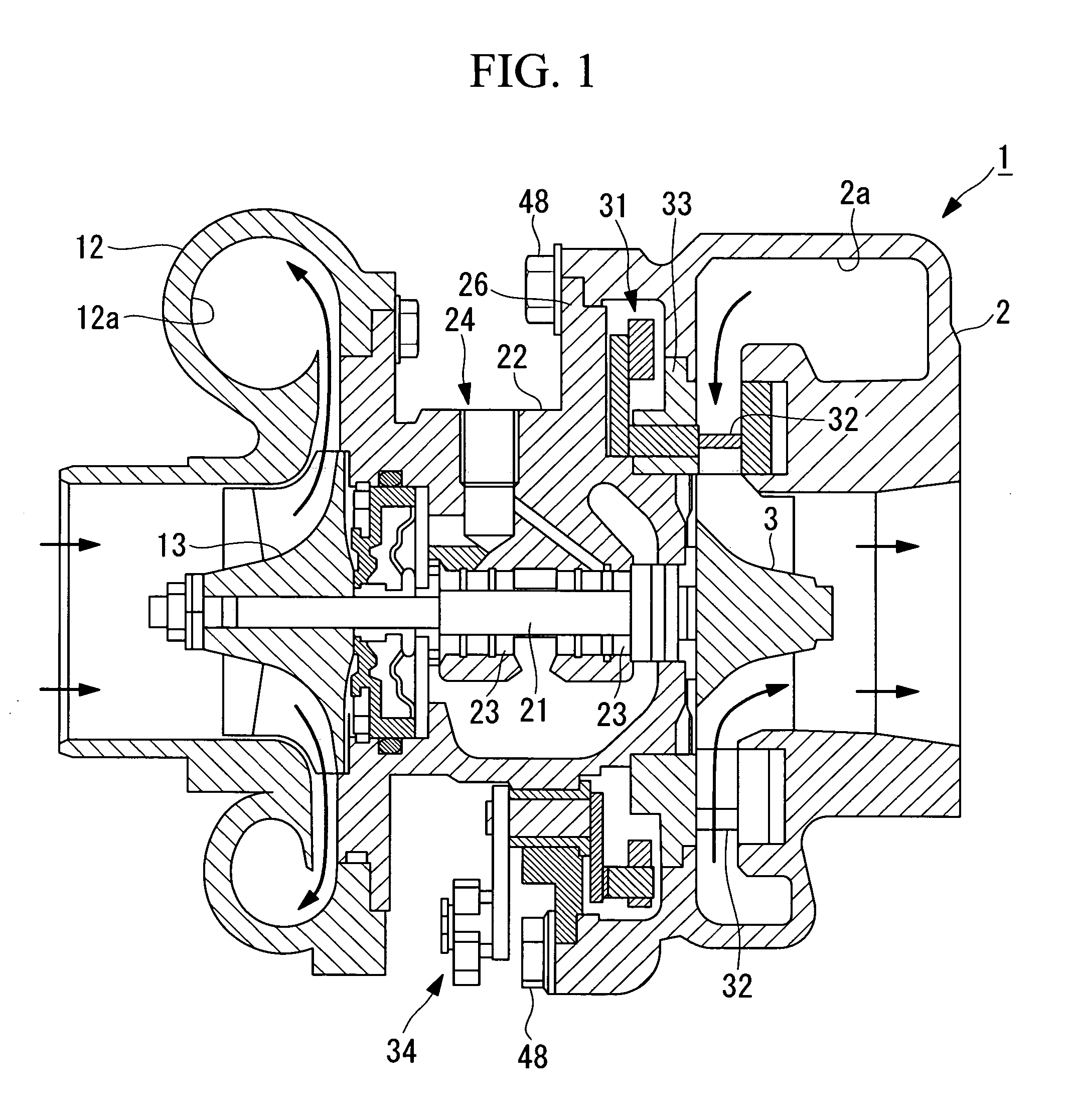
[0130]Hereunder, a first embodiment of the present invention is described, with reference to FIG. 1 and FIG. 2. In the present embodiment, an example in which the present invention is applied to a VG exhaust turbo supercharger is described. The present invention is not limited to this example and may be applied to a generic exhaust turbo supercharger.
[0131]As shown in the vertical sectional view of FIG. 1, an exhaust turbo supercharger 1 according to the present embodiment has a turbine housing 2 inside of which there is formed a spiral flow passage 2a, and a turbine wheel 3, which is provided in a substantially radial direction center section of this turbine housing 2. Into the spiral flow passage 2a of the turbine housing 2, exhaust gas from an internal combustion engine (not shown in the drawing) is supplied. The turbine wheel 3 is rotation driven by exhaust gas supplied into this spiral flow passage 2a. Here, material of the turbine wheel is generic heat resistantalloy.
[0132]Mo...
second embodiment
[0155]Next, a second embodiment of the present invention is described, with reference to FIG. 4.
[0156]An exhaust turbo supercharger 51 according to the present embodiment is an exhaust turbo supercharger shown in the first embodiment, in which the structure for connecting the turbine housing 2 and the bearing housing 22 has been modified. Hereunder, the same reference symbols are assigned to constructions similar to, or the same as, those in the first embodiment, and detailed descriptions thereof are omitted.
[0157]In this exhaust turbo supercharger 51, a turbine housing 52 is used instead of the turbo housing 2. The turbine housing 52 is a turbine housing 2 as shown in the first embodiment, in which, instead of the blind bolt insert hole 46, there is provided a through hole 56 through which the bolt 48 is inserted.
[0158]In this exhaust turbo supercharger 51, by inserting the bolt 48 through the through hole 56 of the turbine housing 52 and engaging the nut 57 with the tip end of the...
third embodiment
[0164]Next, a third embodiment of the present invention is described, with reference to FIG. 5 and FIG. 6.
[0165]An exhaust turbo supercharger 61 according to the present embodiment is characterized mainly in that a turbine housing 62 is used instead of the turbine housing 2 in the exhaust turbo supercharger 1 as shown in the first embodiment. Hereunder, the same reference symbols are assigned to constructions similar to, or the same as, those in the first embodiment, and detailed descriptions thereof are omitted.
[0166]The turbine housing 62 is a turbine housing 2 as shown in the first embodiment in which, instead of the bolt insert hole 46, there is provided a screw hole 66 with which the bolt 48 is engaged. Moreover, in the turbine housing 62, heat radiating fins 67 are provided in the vicinity of the screw hole 66. In the present embodiment, as shown in FIG. 6, in the turbine housing 62, an area in which the screw hole 66 is formed has a shape that projects toward the outer periph...
PUM
Abstract
An exhaust turbo supercharger is provided that is able to effectively prevent exhaust gas that has flowed into between a turbine housing and a bearing housing from leaking to outside of the device, while allowing an excellent level of workability in assembly and disassembly. Included is a turbine housing, into which exhaust gas from an internal combustion engine is introduced; a turbine wheel which is provided within the turbine housing and which is rotation-driven by the exhaust gas; a turbine shaft, one end of which is inserted into the turbine housing, and to which the turbine wheel is attached; a bearing which supports the turbine shaft; and a bearing housing which is connected to the turbine housing and inside of which the bearing is housed. A bolt insert hole is formed in the turbine housing, and an internal thread insert made from a heat insulating material is provided in the bolt insert hole, and the turbine housing and the bearing housing are fixed by a bolt that engages with the internal thread insert.
Description
TECHNICAL FIELD[0001]The present invention relates to an exhaust turbo supercharger to be used in an internal combustion engine that serves as a power source in a vessel, motor vehicle or power generator, in particular, to a VG (variable geometry) type exhaust turbo supercharger.BACKGROUND ART[0002]An exhaust turbo supercharger improves the combustion efficiency of an internal combustion engine by forcefully supplying air into a combustion chamber of the internal combustion engine to improve output of the internal combustion engine and improve the properties of exhaust gas of the internal combustion engine.[0003]As such an exhaust turbo supercharger, a variable displacement type exhaust turbo supercharger disclosed in Patent Document 1 mentioned later is commonly known for example.[0004]This variable displacement type exhaust turbo supercharger has a turbine housing (turbine casing), inside of which there is formed a spiral flow passage, and a turbine wheel provided substantially in...
Claims
Application Information
Patent Timeline
Application Date:The date an application was filed.
Publication Date:The date a patent or application was officially published.
First Publication Date:The earliest publication date of a patent with the same application number.
Issue Date:Publication date of the patent grant document.
PCT Entry Date:The Entry date of PCT National Phase.
Estimated Expiry Date:The statutory expiry date of a patent right according to the Patent Law, and it is the longest term of protection that the patent right can achieve without the termination of the patent right due to other reasons(Term extension factor has been taken into account ).
Invalid Date:Actual expiry date is based on effective date or publication date of legal transaction data of invalid patent.

