Thermal Energy Storage Apparatus

Active Publication Date: 2020-03-19
CLIMATE CHANGE TECH
View PDF0 Cites 0 Cited by
  • Summary
  • Abstract
  • Description
  • Claims
  • Application Information

AI Technical Summary

Benefits of technology

[0019]wherein separation of side walls of the or each receptacle progressively increases as they extend upwardly from the base, where

Problems solved by technology

However, consistency of supply and electricity grid stability is a major issue with renewables.
For example, by its very nature, solar energy's biggest pitfall is the fact that at certain times of the day, the sun is unable to provide the necessary flux of photons to various devices that utilise solar energy.
Similarly, wind-turbines and the like are only effective when there is sufficient wind strength to drive them.
Interrupted or inconsistent supply of energy from a source makes it, in many instances, unreliable and also uneconomical, thereby limiting the potential use of the source.
In addition, at certain times, the sun's rays can be so excessive that the resultant heat and energy are dissipated as over-supply, rather than being usable by a solar-powered device.
A disadvantage of silicon metalloid material is that it requires significant care and understanding of its physical transformation during its expansion and contraction as it absorbs and rele

Method used


Image

  • Thermal Energy Storage Apparatus
  • Thermal Energy Storage Apparatus
  • Thermal Energy Storage Apparatus

Examples


Example

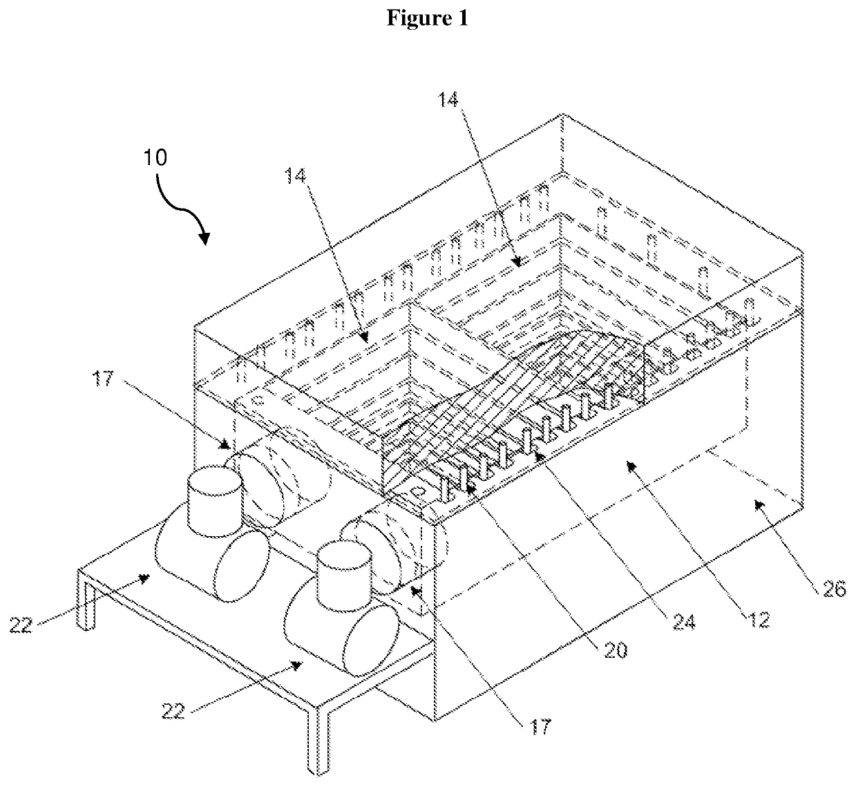
[0036]Referring initially to FIG. 1, there is shown a thermal energy storage apparatus 10 according to a preferred embodiment of the present invention.

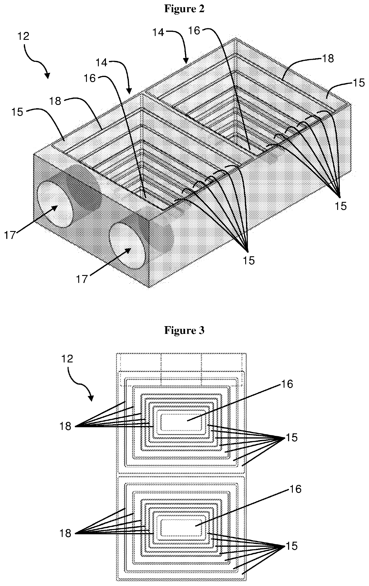
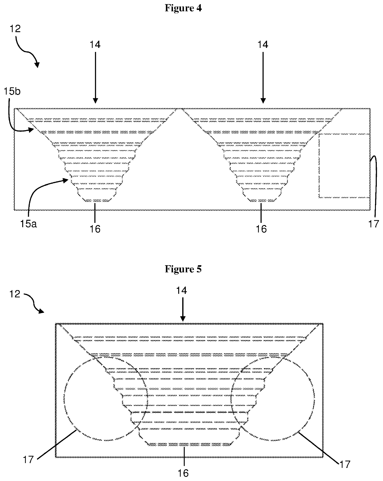
[0037]The thermal energy storage apparatus 10 includes a block 12 of a heat-absorbing material. As illustrated in FIGS. 2 to 5, the block 12 defines at least one receptacle 14 in which phase change material can be received. In this regard, the block 12 may be formed with a single receptacle as illustrated in FIGS. 10 to 12, twin receptacles as illustrated in FIGS. 2 to 9, or greater than two receptacles. The block 12 is a contiguous block of compressed sintered graphite which is machinable.

[0038]As used herein, the term “contiguous” refers to a single mass of material, whether solid or porous, in which any two points within the mass may be joined by a continuous path. By being “contiguous” the block is a single or unitary piece of heat absorbing material. The block is not composed of an assemblage of multiple, discrete pieces of heat ...


PUM


Abstract

A thermal energy storage apparatus, including: a block of a heat-absorbing material, the block defining at least one receptacle and being a contiguous block of compressed sintered graphite; and a phase change material stored in the or each receptacle, the phase change material being one that expands as it cools, wherein separation of side walls of the or each receptacle progressively increases as they extend upwardly from the base, whereby as the phase change material solidifies and expands it is urged upwardly to reduce pressure applied to the heat-absorbing material.

Description

FIELD OF THE INVENTION[0001]The present invention relates to a thermal energy storage apparatus.BACKGROUND OF THE INVENTION[0002]There has been a push in recent years to move away from fossil fuels as an energy source. The move towards what are generally characterised as “renewables” or cleaner fuel sources has seen significant development in the use of solar or wind energy as a means of providing usable forms of energy.[0003]However, consistency of supply and electricity grid stability is a major issue with renewables. For example, by its very nature, solar energy's biggest pitfall is the fact that at certain times of the day, the sun is unable to provide the necessary flux of photons to various devices that utilise solar energy. Similarly, wind-turbines and the like are only effective when there is sufficient wind strength to drive them.[0004]Interrupted or inconsistent supply of energy from a source makes it, in many instances, unreliable and also uneconomical, thereby limiting t...

Claims


Application Information

Patent Timeline
IPC IPC(8): F28D20/02F02G1/04
CPCF02G1/04F28D20/023C09K5/06F01K3/02F01K3/12F01K3/186F28F21/02F28D20/021F28D2020/0082Y02E10/46Y02E60/14
Inventor WARBURTON, GRAHAMPARKINSON, NEIL
Owner CLIMATE CHANGE TECH
Why Eureka
Try Eureka