Non-contact type rotational angle detection apparatus and manufacturing method thereof

a technology of rotational angle detection and manufacturing method, which is applied in mechanical devices, machines/engines, instruments, etc., can solve the problems of low rust resistance performance of permanent magnets, low productivity, and possible generation of rust, so as to reduce the number of component parts required, prevent relative displacement, and improve productivity

Inactive Publication Date: 2009-06-18
MITSUBISHI ELECTRIC CORP
View PDF12 Cites 17 Cited by
  • Summary
  • Abstract
  • Description
  • Claims
  • Application Information

AI Technical Summary

Benefits of technology

[0019]According to the non-contact type rotational angle detection apparatus in the first aspect of the present invention, the cylindrical yoke is fixedly secured by shrinkage fitting to the cylindrical permanent magnet which is disposed at the inner side of the yoke, and the engagement margin between the permanent magnet and the yoke is set equal to or greater than the value with which a relative displacement between the permanent magnet and the yoke due to the molding pressure of the resin is restrained. With such an arrangement, it is possible to reduce the number of component parts required, to improve productivity, and to prevent the relative displacement between the permanent magnet and the yoke.
[0020]According to the non-contact type rotational angle detection apparatus i

Problems solved by technology

With the non-contact type rotational angle detection apparatus as constructed above, however, there are the following problems.
It is necessary to assemble the two polarized permanent magnets to each other, so handling these permanent magnets is very difficult due to the discrimination of polarization thereof, the magnetic attrac

Method used


Image

  • Non-contact type rotational angle detection apparatus and manufacturing method thereof
  • Non-contact type rotational angle detection apparatus and manufacturing method thereof
  • Non-contact type rotational angle detection apparatus and manufacturing method thereof

Examples


embodiment 1

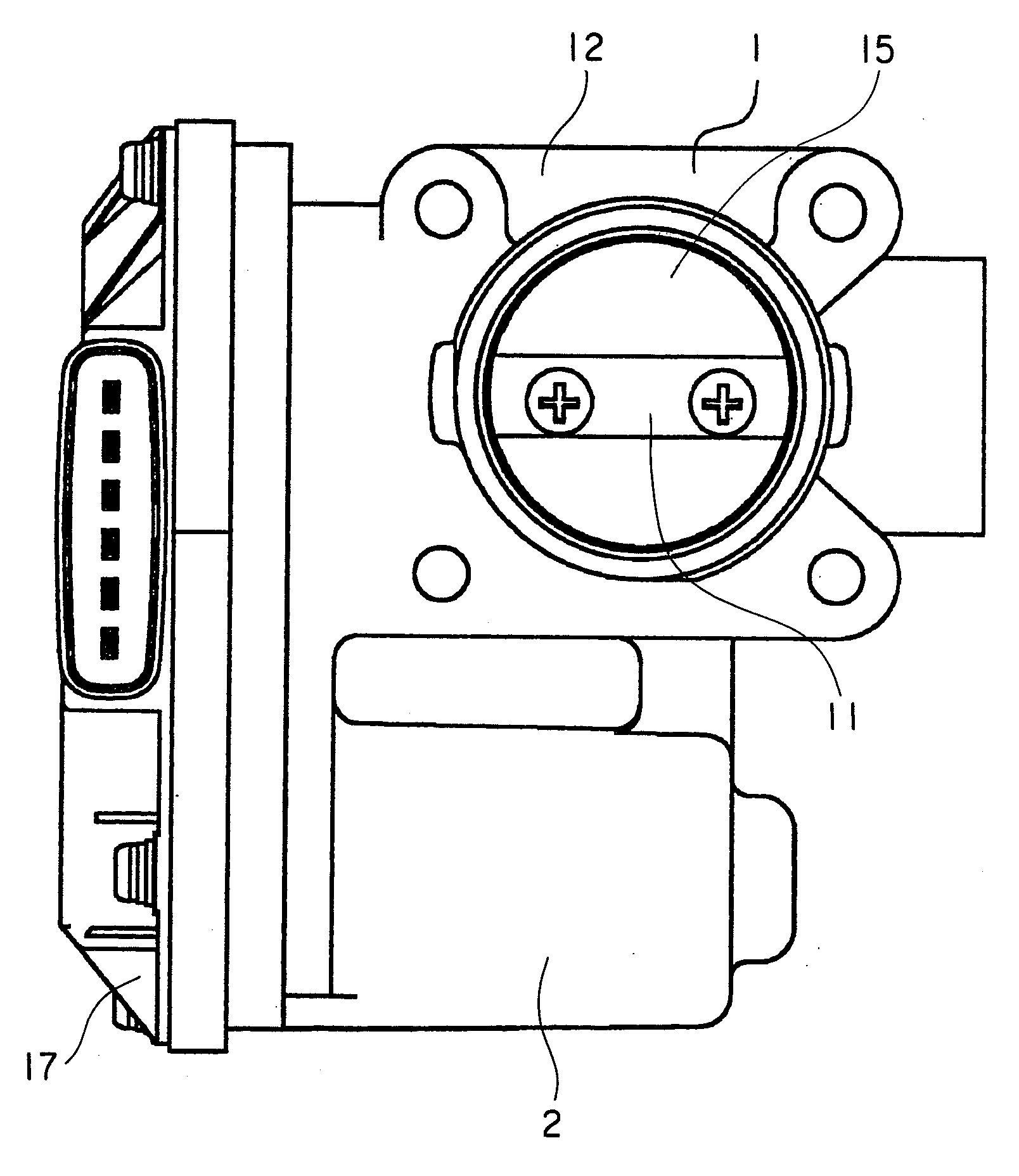
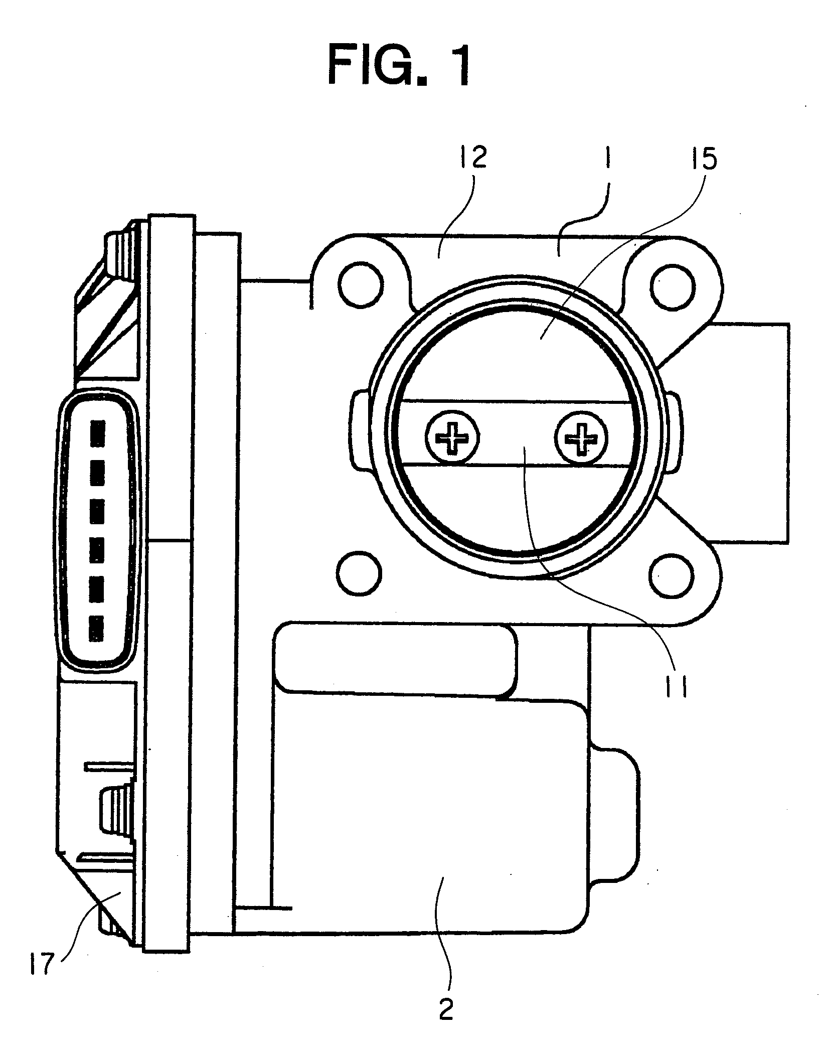
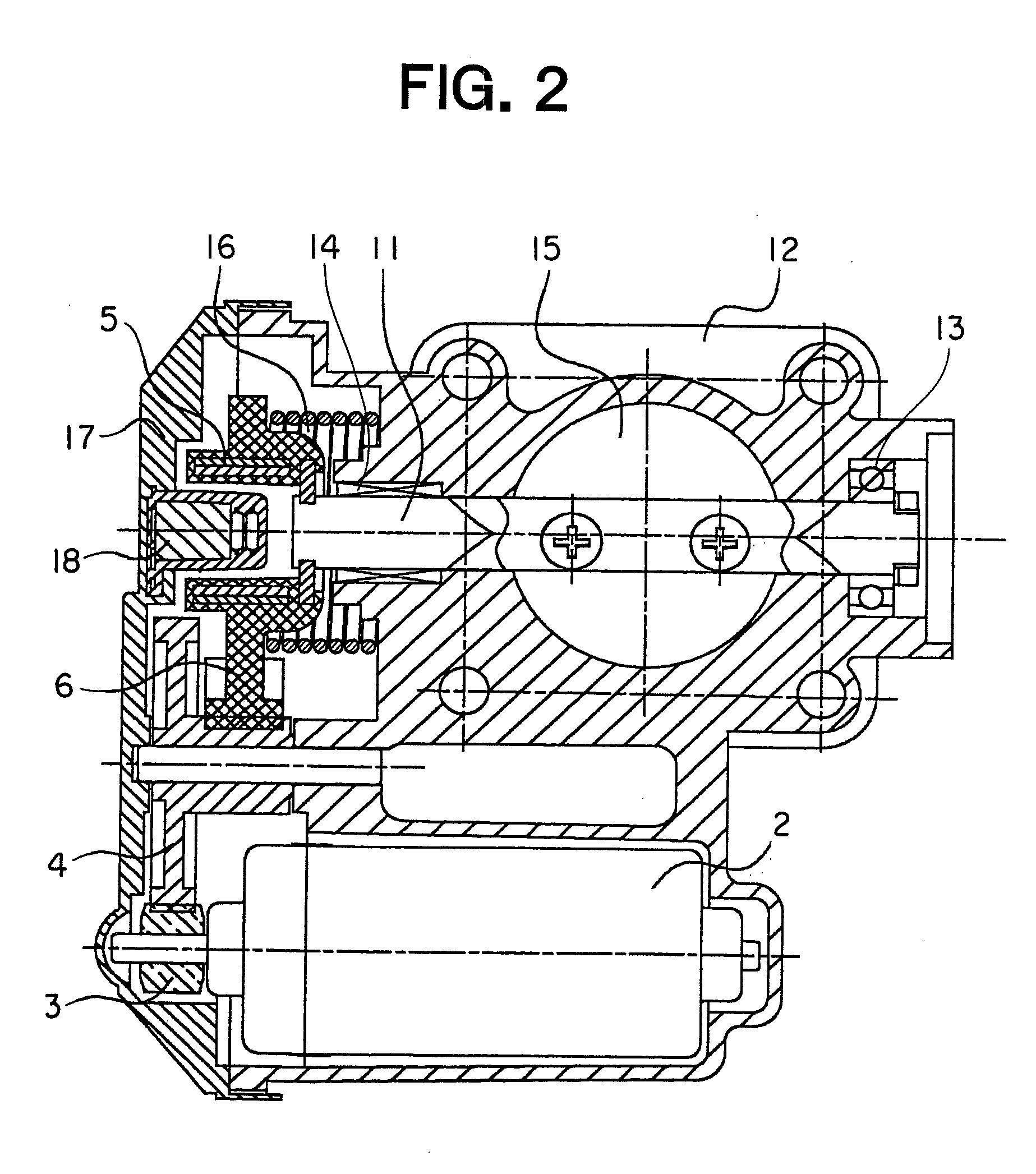
[0034]Referring to the drawings and first to FIG. 1, there is shown, in a front elevational view, an intake air control system for an engine (hereinafter referred to simply as an intake air control system) into which a non-contact type rotational angle detection apparatus (hereinafter referred to simply as a rotational angle detection apparatus) according to a first embodiment of the present invention is built. FIG. 2 is a cross sectional front view that shows the intake air control apparatus designated at a reference numeral 1 in FIG. 1.

[0035]In this intake air control system 1, a motor gear 3 is fixedly mounted on a rotation or output shaft of a drive motor 2 which is driven to rotate by direct current supplied thereto from an electric power supply (not shown). The motor gear 3 is in meshing engagement with a speed reduction gear 4 made of resin. A throttle gear 6 of an insert molded body 5 is in meshing engagement with the speed reduction gear 4.

[0036]FIG. 3 is a cross sectional ...

embodiment 2

[0066]FIG. 10 is an enlarged cross sectional view of essential parts that shows a non-contact type rotational angle detection apparatus according to a second embodiment of the present invention.

[0067]In this second embodiment, there is an all-around clearance A between the outer peripheral surface of the permanent magnet 8 and the inner peripheral surface of the yoke 9. The other construction of this second embodiment is similar to that of the first embodiment.

[0068]If the clearance A exceeds a proper range, the permanent magnet 8 will be damaged by the molding pressure generated at the time of resin molding. That is, when insert molding is carried out after the cylindrical permanent magnet 8 and the cylindrical yoke 9 are combined or assembled with each other, the molding pressure generated at this time is mainly applied to the permanent magnet 8 in a direction from an inner peripheral side to an outer peripheral side thereof, and is also applied to the yoke 9 in a direction from a...


PUM

PropertyMeasurementUnit
Lengthaaaaaaaaaa
Angleaaaaaaaaaa
Shrinkageaaaaaaaaaa

Abstract

A non-contact type rotational angle detection apparatus can reduce the number of parts required, improve productivity, and prevent a relative displacement between a permanent magnet and a yoke. An insert molded body is fixedly secured to a shaft and is composed of a permanent magnet and a yoke formed integrally with each other by insert molding of a resin. A non-contact sensor is disposed in an inner space formed in the insert molded body. The non-contact sensor detects a rotation angle of the shaft by detecting an azimuth of magnetic flux lines generated by the permanent magnet. The cylindrical yoke is fixedly secured by shrinkage fitting to the cylindrical permanent magnet disposed at an inner side thereof. An engagement margin between the permanent magnet and the yoke is set equal to or greater than a value which restrains a relative displacement between the permanent magnet and the yoke.

Description

BACKGROUND OF THE INVENTION[0001]1. Field of the Invention[0002]The present invention relates to a non-contact type rotational angle detection apparatus and a manufacturing method thereof in which the rotation angle of a rotatable member such as for example a throttle valve by detecting a change in the azimuth of magnetic flux.[0003]2. Description of the Related Art[0004]In the past, there has been known a non-contact type rotational angle detection apparatus in which the rotational angle of a throttle valve, which is used to achieve the control of an optimal amount of air with respect to an amount of fuel to be injected into an engine, is detected from the point of view of the improvement in fuel mileage of the engine, countermeasures for exhaust emissions regulations, and the improvement in running stability of a vehicle (see, for example, a first patent document: Japanese patent application laid-open No. 2004-84503).[0005]In such a non-contact type rotational angle detection appa...

Claims


Application Information

Patent Timeline
IPC IPC(8): G01B7/30B29C65/70
CPCF02D9/105Y02T10/121G01B7/30F02M25/0756F02M26/48
Inventor NAGAHORI, TATSUROKURITA, KAZUHISATAKAGI, KATSUNARIMORIGUCHI, TERUHIKO
Owner MITSUBISHI ELECTRIC CORP
Why Eureka
Try Eureka