Eureka AIR delivers breakthrough ideas for toughest innovation challenges, trusted by R&D personnel around the world.

Folding crank handle for hose reel

Active Publication Date: 2009-06-18
IAMS
View PDF4 Cites 24 Cited by
  • Summary
  • Abstract
  • Description
  • Claims
  • Application Information

AI Technical Summary

Benefits of technology

[0008]These needs, and others, are met by at least one embodiment of the claimed invention wherein a crank assembly has a crank arm with a handle member pivotally coupled thereto. The handle member includes a lock assembly with a crank component and a handle component. The crank component includes a latch surface on a crank arm outer surface. The lock assembly handle component is, preferably, at least one extension extending from the handle member and structured to engage the latch surface. The lock assembly handle component further has a release device structured to disengage the at least one extension from the latch surface. The release device is accessible from the crank arm outer surface. In this configuration, a user may easily access the release device because the release device is located on the outer surface of the crank arm.

Problems solved by technology

While manufacturers try to make the assembly of a typical hose reel relatively simple, there are many components of a hose reel assembly that are difficult for some users to install or assemble.
The disadvantage to having preinstalled components, however, is that some components, especially those like the crank handle that extend away from the body of the hose reel, require additional room in the shipping container and / or storage box.
Unfortunately, these structures were also designed to snap into an extended position and not be collapsed again.
The release devices, however, were typically hard to reach and difficult to actuate.
Given that the handle is disposed immediately adjacent to the housing assembly, accessing the locking tab could be difficult.

Method used


Image

  • Folding crank handle for hose reel
  • Folding crank handle for hose reel
  • Folding crank handle for hose reel

Examples


Embodiment Construction

[0016]As used herein, the word “unitary” means a component is created as a single piece or unit. That is, a component that includes pieces that are created separately and then coupled together as a unit is not a “unitary” component or body.

[0017]As used herein, a “uniform surface” has generally the same texture across the surface. Such a “uniform surface” may be smooth or uniformly textured. A “uniform surface” does not have any localized pits, detents, or deformations.

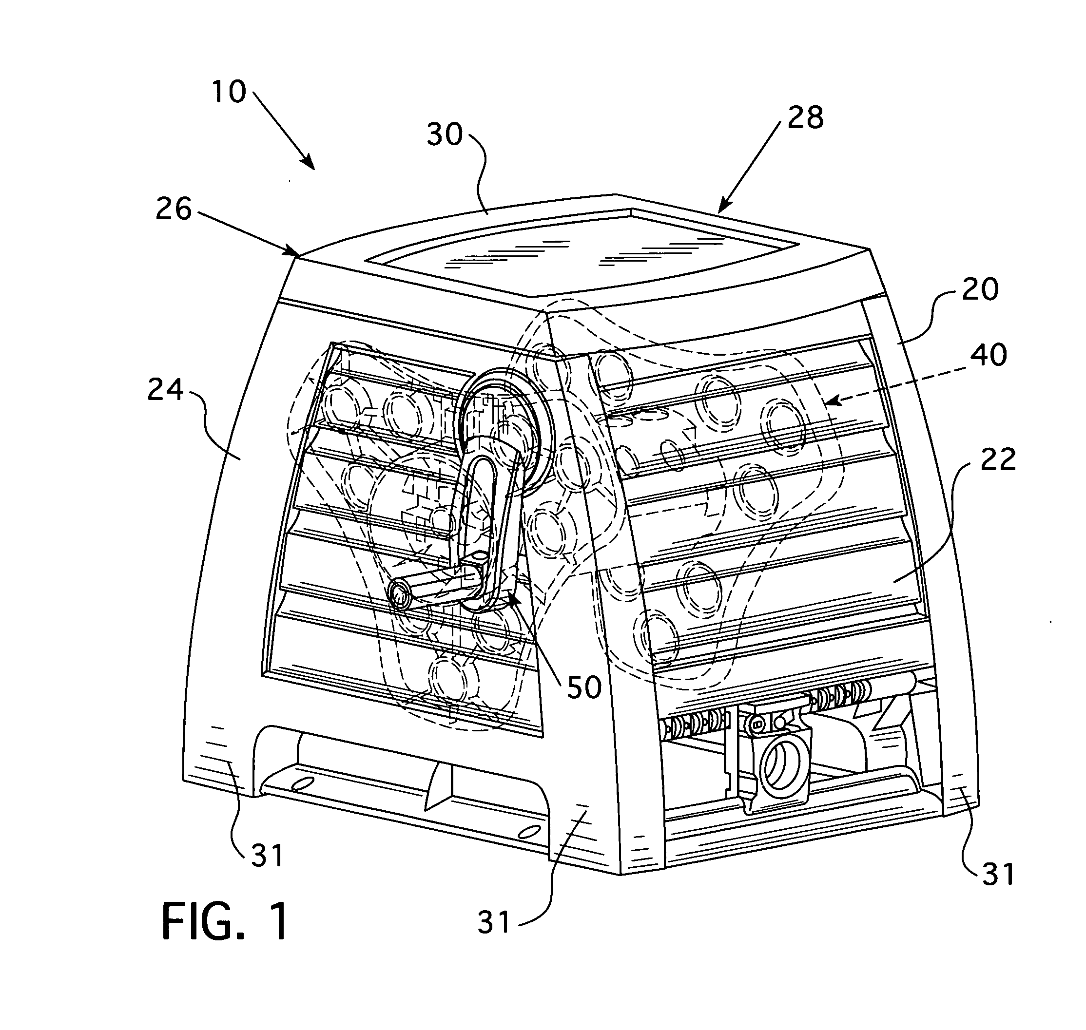
[0018]As shown in FIG. 1, a hose reel assembly 10 includes a housing assembly 20 and a basket assembly 40. The housing assembly 20 may be a frame (not shown) but is shown as including a front side 22, a first lateral side 24, a back side 26, a second lateral side 28, and a top member 30. The front side 22 and the back side 26 are each coupled to the first and second lateral sides 24, 28 and disposed in a spaced, generally parallel configuration. The first and second lateral sides 24, 28 are also disposed in a spaced, ...


PUM


Abstract

A crank assembly having a crank arm with a handle member pivotally coupled thereto is provided. The handle member includes a lock assembly with a crank component and a handle component. The crank component includes a latch surface on a crank arm outer surface. The lock assembly handle component is, preferably, at least one extension extending from the handle member and structured to engage the latch surface. The lock assembly handle component further has a release device structured to disengage the at least one extension from the latch surface. The release device is accessible from the crank arm outer surface. In this configuration, a user may easily access the release device because the release device is located on the outer surface of the crank arm.

Description

BACKGROUND OF THE INVENTION[0001]1. Field of the Invention[0002]The present invention relates to a hose reel and, more specifically, to a folding crank handle for a hose reel.[0003]2. Background Information[0004]Hose reel assemblies are devices structured to assist in transporting and using hoses, typically garden hoses for dispensing water. Generally, the hose reel assembly includes a base, frame, or housing assembly structured to rotatably support a reel, or “basket assembly.” The basket assembly's primary components are a barrel, around which an outlet hose is wrapped, two hubs which are coupled to the housing assembly, and guide plates which define the usable area of the barrel. The basket assembly also includes a crank, used to turn the basket primary components, and a water conduit having a movable outlet and a generally stationary inlet. The stationary inlet of the conduit extends away from the reel and is structured to be coupled to a supply hose which is further coupled to ...

Claims


Application Information

Patent Timeline
IPC IPC(8): F16H21/18B65H75/38
CPCB65H75/40B65H2402/412B65H2701/33Y10T74/18232B65H75/4471B65H75/4494G05G1/085Y10T137/6954
Inventor MULLEN, JOSHUA O.HATCHER, STEPHEN D.
Owner IAMS
Why Eureka
Eureka Blog
Learn More