Eureka AIR delivers breakthrough ideas for toughest innovation challenges, trusted by R&D personnel around the world.

Polyphonic sound generating method

a polyphonic sound and polyphonic sound technology, applied in the field of polyphonic sound generation, can solve the problems of inability to produce a monophonic sound of mediocre musicality, duration variation, etc., and achieve the effect of reducing the duty cycle of the logic control signal reducing the duty cycle of the piezoelectric transducer, and saving energy

Inactive Publication Date: 2009-06-18
ASULAB SA
View PDF3 Cites 3 Cited by
  • Summary
  • Abstract
  • Description
  • Claims
  • Application Information

AI Technical Summary

Benefits of technology

[0009]Owing to these features, the present invention allows considerable energy savings to be achieved, which proves particularly advantageous if the piezoelectric transducer is fitted to a portable instrument, such as a wristwatch or a mobile telephone, whose energy storage capacity is limited. It has been observed that reducing the duty cycle of the piezoelectric transducer logic control signal, in other words reducing the active phase of the signal and thus the electric power consumption, nonetheless allows acceptable acoustic properties (sound level, tone) to be maintained.
[0010]Above all, reduction of the piezoelectric transducer logic control signal duty cycle makes it possible to envisage generating a polyphonic sound.

Problems solved by technology

The drawback of this system is that it is only capable of generating a monophonic sound of mediocre musicality and which has virtually no variations.
Consequently, the method used (pulse duration variation) also does not enable a polyphonic sound to be produced, but only a sound with a variable timbre, which remains monophonic in nature.

Method used


Image

  • Polyphonic sound generating method
  • Polyphonic sound generating method

Examples


Embodiment Construction

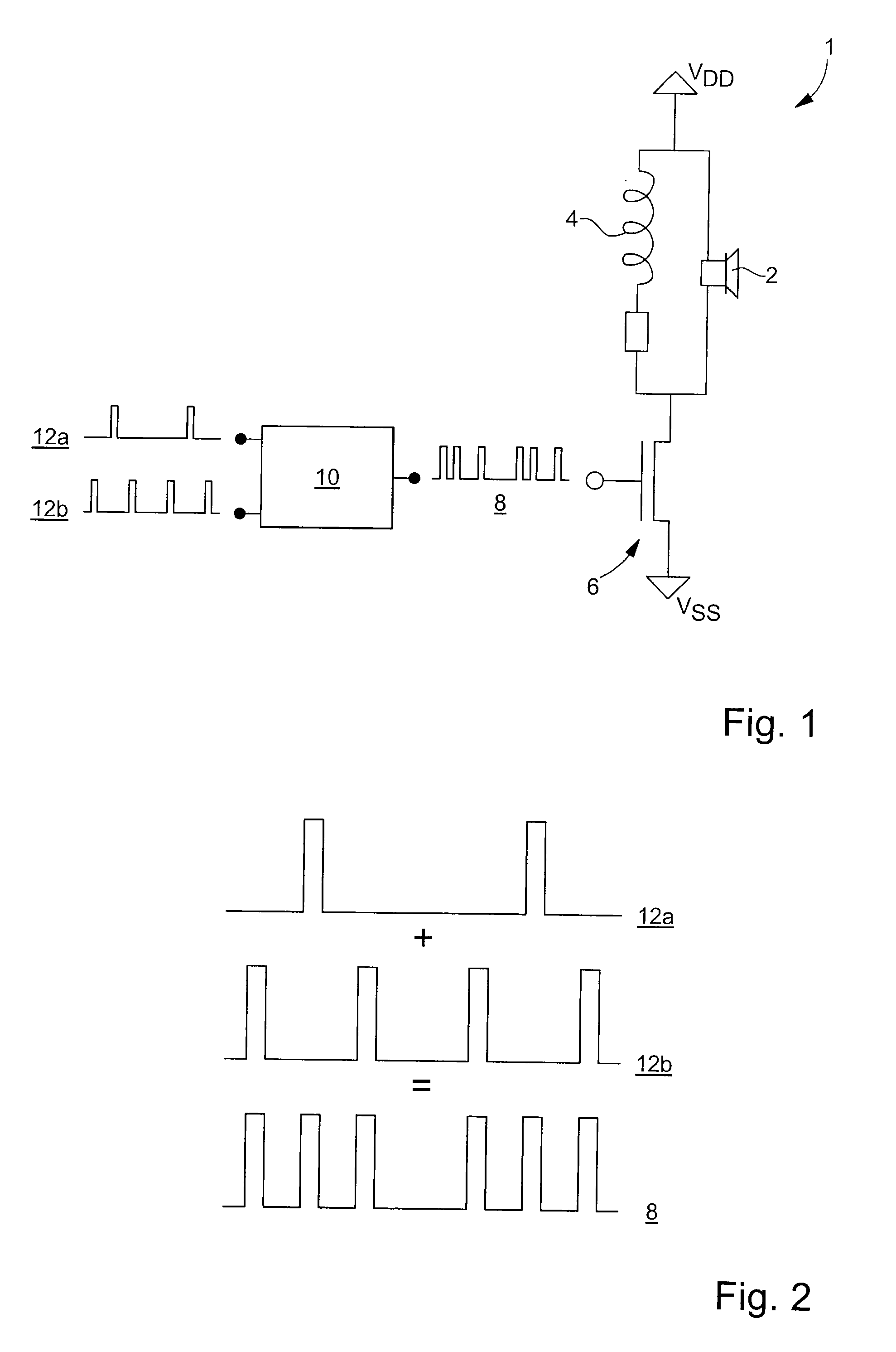
[0016]The present invention proceeds from the general inventive idea that consists in controlling an acoustic piezoelectric transducer by means of an undulating type logic signal whose pulse duration is fixed and whose duty cycle is less than 0.5. Reducing the pulse duration reduces the active phase of the logic signal and thus the electric power consumption, while keeping acceptable acoustic properties. Moreover, by selecting a duty cycle of less than 0.5, one can simultaneously superpose several tracks of different frequencies and thus produce a polyphonic sound.

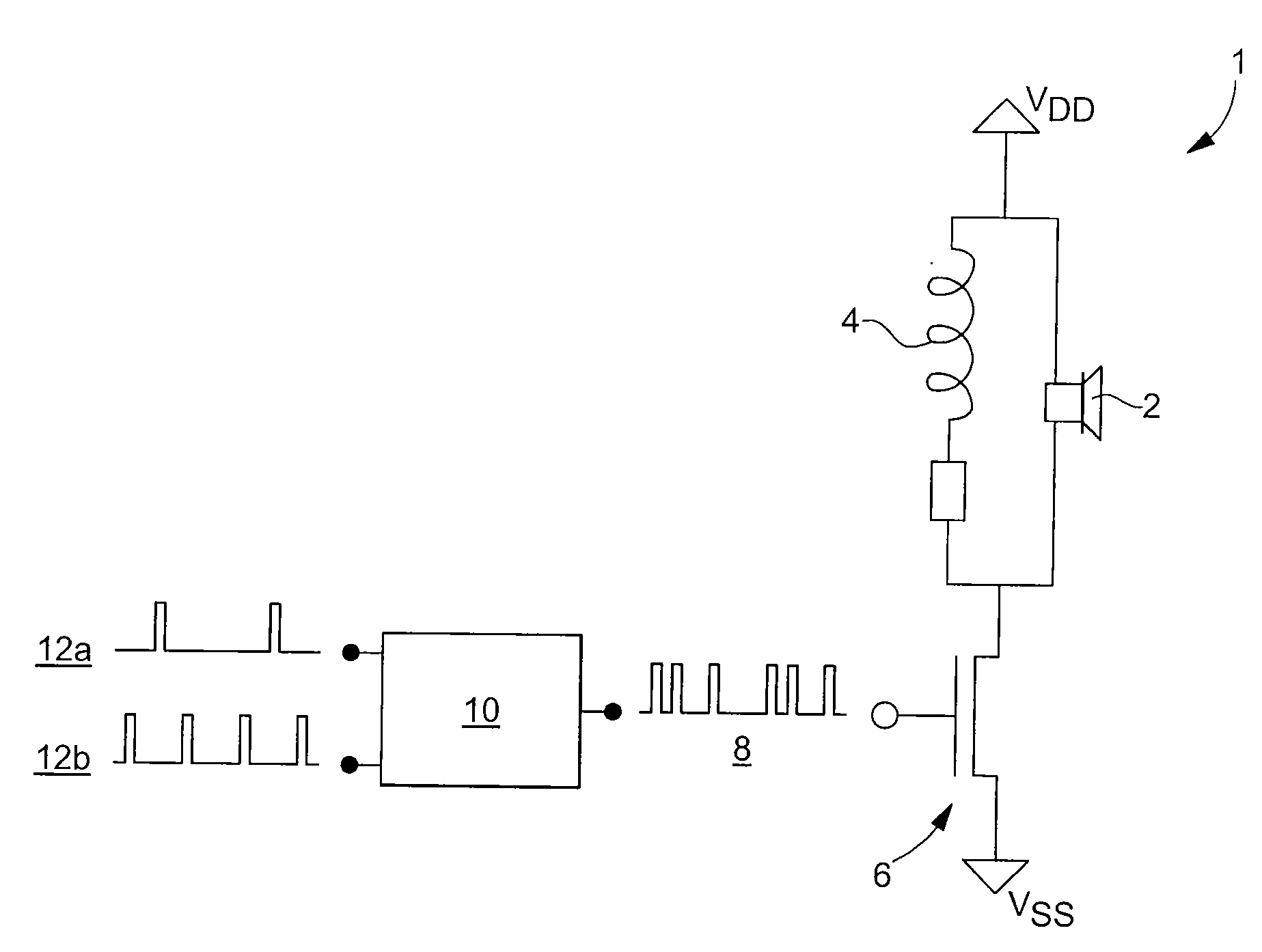
[0017]FIG. 1 is a schematic diagram of a drive circuit for a piezoelectric type acoustic transducer. Designated as a whole by the general reference numeral 1, this drive circuit includes a piezoelectric element 2 and a booster coil 4 connected in parallel on the collector side of an amplification transistor 6. When an electric signal 8 is applied to the base of transistor 6, the latter becomes conductive and the current fl...


PUM


Abstract

Method of driving an acoustic piezoelectric transducer (6) characterized in that a signal (8), resulting from the time multiplexing of at least two rectangular periodic signals (12a, 12b) of different frequencies and having pulses of fixed duration and whose duty cycle is less than 0.5, is applied to the terminals of the transducer (6). This signal may result from the time sum of at least two undulating logic signals of different durations.

Description

[0001]This is a National Phase Application in the United States of International Patent Application No. PCT / EP2005 / 012169 filed Nov. 14, 2005, which claims priority on European Patent Application No. 04028421.8, filed Dec. 1, 2004. The entire disclosures of the above patent applications are hereby incorporated by reference.FIELD OF THE INVENTION[0002]The present invention concerns a method of generating a polyphonic sound by means of a piezoelectric type acoustic transducer.BACKGROUND OF THE INVENTION[0003]Generation of an alarm sound using a piezoelectric vibrator is known, particularly in the wristwatch field. The drive device for this type of vibrator conventionally comprises a piezoelectric element and a booster coil connected in parallel on the collector side of an amplification transistor. When an electric control signal is applied to the base of the transistor in order to make the latter conductive, the current flows through the electric coil in response to the closing of sai...

Claims


Application Information

Patent Timeline
Patent Type & Authority Applications(United States)
IPC IPC(8): G06G7/14
CPCB06B1/0276B06B1/02B06B1/06
Inventor AEBY, FABIEN
Owner ASULAB SA
Why Eureka
Eureka Blog
Learn More