
Smart Card System With Ergonomic Fingerprint Sensor And Method of Using

a fingerprint sensor and ergonomic technology, applied in the field of smart card systems with ergonomic fingerprint sensors and methods of using, can solve the problems of low-cost devices, easy to misuse smart cards, and large size and cost of such sensors,

Inactive Publication Date: 2009-06-18
SYNAPTICS INC
View PDF100 Cites 209 Cited by
  • Summary
  • Abstract
  • Description
  • Claims
  • Application Information

AI Technical Summary

Benefits of technology

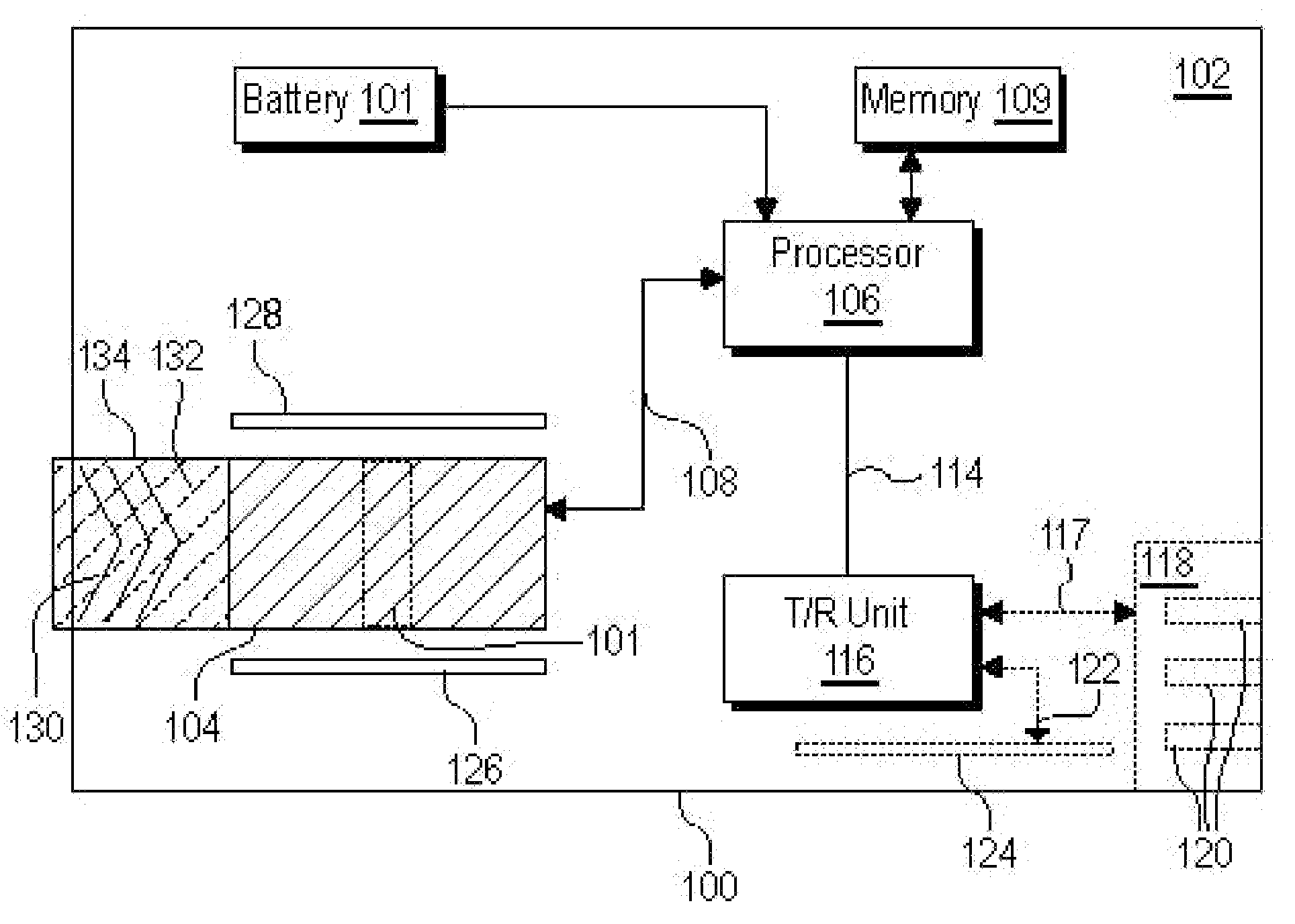
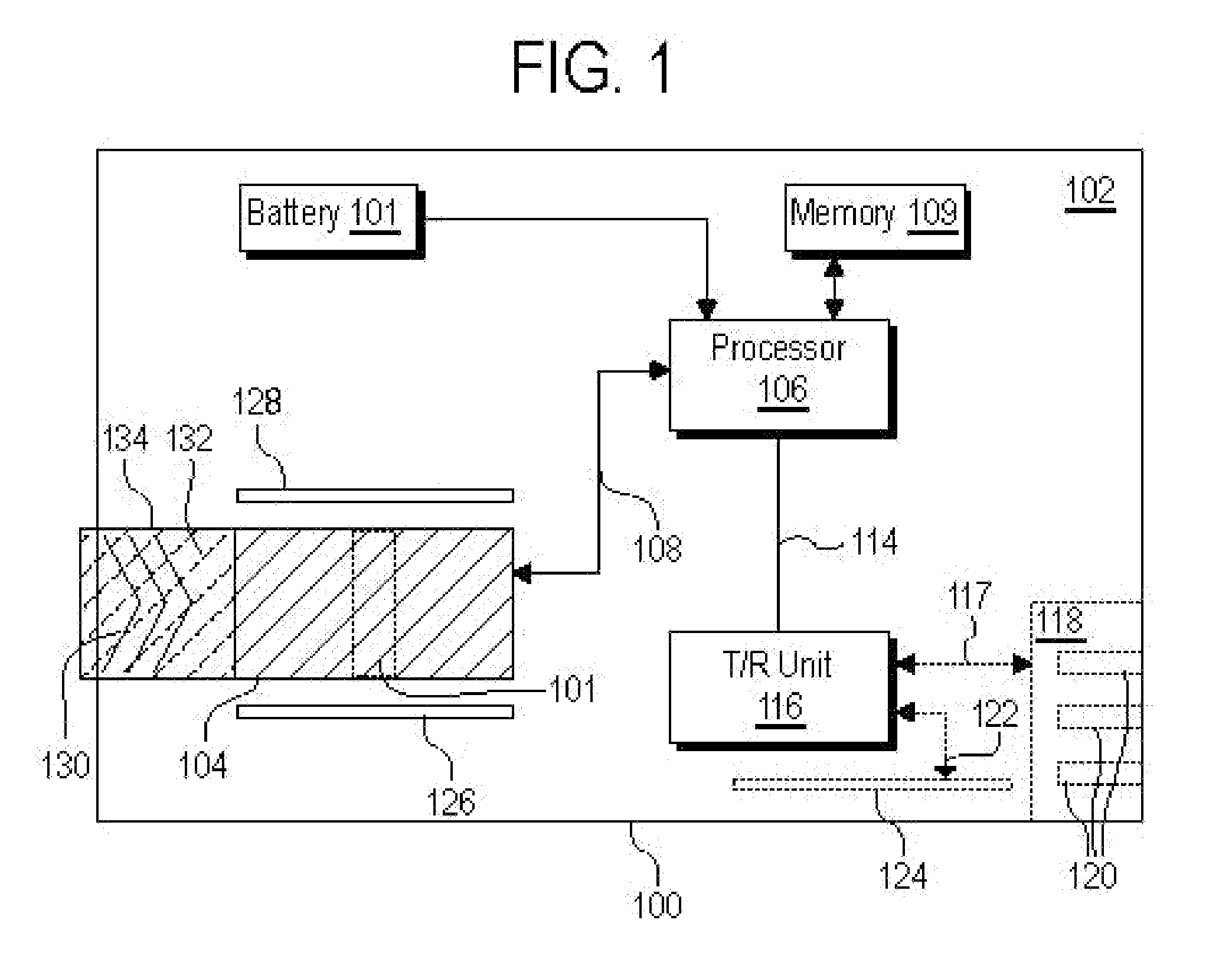
[0017]The present invention discloses a small unitized device with an embedded fingerprint reader, such as unitized smart card device, which also contains various ergonomic guides to help ensure that the fingerprint sensor is used (swiped) in a correct manner. Usually the smart card will additionally contain secure memory that contains confidential information, such as financial information, passwords, encryption information in the like. The smart card will also usually contain an onboard processor to run the fingerprint sensor, and this onboard processor will partially or fully unlock the contents of the smart card's secure memory if the card's onboard fingerprint sensor detects that an authorized user has accessed the device. The smart card may also contain a battery.

Problems solved by technology

If misappropriated, such devices can give an unauthorized user free phone system access, access to private telephone numbers and contact information, internet access, and access to other sensitive information.
To improve security, fingerprint sensors are highly useful, however the size and cost of such sensors is often prohibitive in such very small, low-cost devices.
One of the major ways that a smart card can be misused is through physical theft, where a smart card simply falls into the hands of an unauthorized user.
Although attractive, the technical challenges of implementing fingerprint sensors into smart cards are substantial.
Even if the thickness specification is relaxed to several mm, such as 5 mm or less, Fitting a fingerprint scanner and associated circuitry into such a small space is challenging.
An additional problem is that smart cards typically are subjected to demanding environmental conditions, such as being stored and retrieved from a wallet for extended periods of time, any sensor and circuitry on such cards must be extremely robust.
Consider the engineering challenges: not only must the fingerprint sensor itself be paper thin and robust (which rules out many types of conventional but bulky or fragile fingerprint sensors), but the associated electronic circuitry, such as the processor, memory, any display device, electrical contact or communication device, and any battery used to power the unit must also be extremely thin.
Small and thin batteries have correspondingly low amounts of stored energy.
However when reading a fingerprint swipe, fingerprint scanners require appreciable amounts of power.
Unfortunately improper fingerprint swipes often use as much power as proper fingerprint swipes.
If, due to ergonomic issues, a user has to make repeated attempts to obtain a valid fingerprint swipe, battery life would suffer, and the practicality of such a smart card for routine, long-term, use would become minimal.
Though many devices exist to sense and record an entire fingerprint, these devices tend to be relatively large.
Again this takes electrical power, which is problematic when battery size is limited.
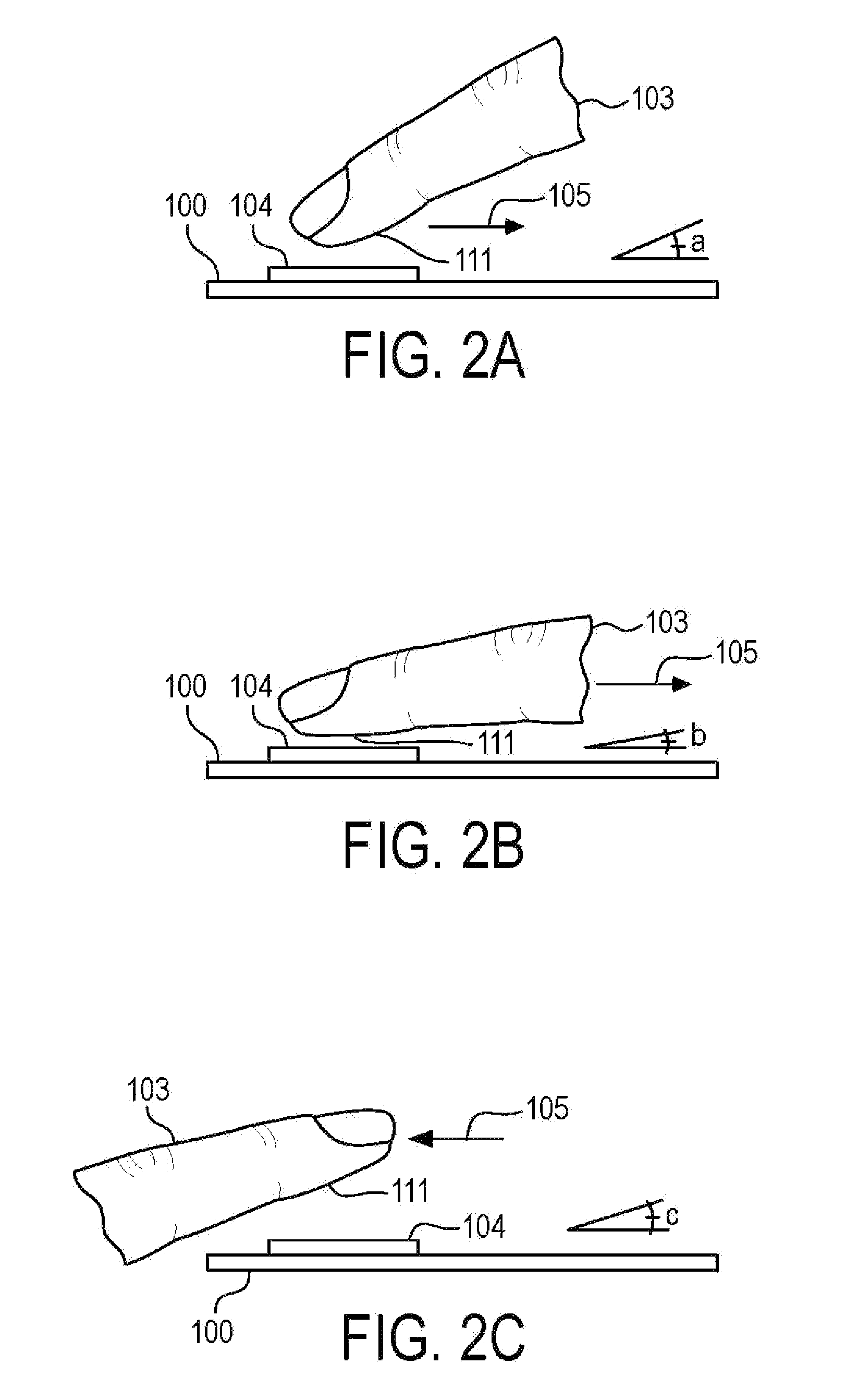
If, for example, a user swipes the finger at one or more improper angles, a poor fingerprint image may be captured.
At a minimum, additional computational time and energy will be needed by any processor that attempts to interpret the image, and more likely, a rescan will be required, significantly lowering battery life and also inconveniencing the user.

Method used


Image

  • Smart Card System With Ergonomic Fingerprint Sensor And Method of Using
  • Smart Card System With Ergonomic Fingerprint Sensor And Method of Using
  • Smart Card System With Ergonomic Fingerprint Sensor And Method of Using

Examples


Embodiment Construction

[0046]Although this invention can work with a wide variety of partial fingerprint sensors, in order to give specific example, much of the discussion will focus on deep finger penetrating radio frequency (RF) sensing technology, such as those manufactured by Validity Sensors, Inc. Thus to begin, this technology will be discussed in more detail.

[0047]Validity partial fingerprint sensors measure the intensity of electric fields conducted by finger ridges and valleys, such as deep finger penetrating radio frequency (RF) based sensing technology, and use this information to sense and create the fingerprint image. These devices create sensing elements by creating a linear array composed of many miniature excitation electrodes, spaced at a high density, such as a density of approximately 500 electrodes per inch. The tips of these electrodes are separated from a single sensing electrode by a small sensor gap. The electrodes are electrically excited in a progressive scan pattern and the ridg...


PUM


Abstract

A unitized smart card device with a partial fingerprint sensor, ergonomic guides and a processor is disclosed. The smart card contains secure memory, battery, and a processor to run the fingerprint sensor. The ergonomic guides help insure that the users finger properly swipes the fingerprint sensor. The smart card be used on a backwards compatible “dumb credit card” basis, or it may dock with an external smart card docking station. This docking station may act to facilitate communication between the smart card's fingerprint sensor and its onboard secure memory; and external computerized devices. The docking station itself may be configured with slots or other openings to allow users to access the smart card's fingerprint sensor while the smart card is docked with the docking station. The docking station itself may contain ergonomic guides to help ensure that the smart card's fingerprint sensor is used (swiped) in a correct manner.

Description

[0001]This application is related to U.S. Non-Provisional application Ser. No. TBD, filed Dec. 14, 2007, entitled “Smart Card System With Ergonomic Fingerprint Sensor And Method of Using,” and U.S. Non-Provisional application Ser. No. TBD, filed Dec. 14, 2007, entitled “Smart Card System and Docking Device With Ergonomic Fingerprint Sensor.”BACKGROUND[0002]Many modern pocket sized devices exist and are being developed that contain or have access to very sensitive information. Examples include cellular phones that can access a cellular network, smart cards, and other hand held pocket sized devices. If misappropriated, such devices can give an unauthorized user free phone system access, access to private telephone numbers and contact information, internet access, and access to other sensitive information. To improve security, fingerprint sensors are highly useful, however the size and cost of such sensors is often prohibitive in such very small, low-cost devices.[0003]Although any typ...

Claims


Application Information

Patent Timeline
Patent Type & Authority Applications(United States)
IPC IPC(8): G06K9/00G05B19/00
CPCG06K9/00026G06K19/07732G06K19/077G06K19/0718G06V40/1335
Inventor GARDNER, LAWRENCE C.
Owner SYNAPTICS INC
Learn More