Liquid crystal display device

Active Publication Date: 2009-06-18
TRIVALE TECH
View PDF11 Cites 18 Cited by
  • Summary
  • Abstract
  • Description
  • Claims
  • Application Information

AI Technical Summary

Benefits of technology

[0006]It is an object of the present invention to provide a liquid crystal display device wherein, in case of providing at least one or more FPCs, by re

Problems solved by technology

However, loosely setting the pitches of the panel connecting terminals will result in a longer lateral width of the FPC and thus in increased costs.
On the other hand, reducing the number of layers constituting the FPC (for instance, when a normal CCL (Copper Clad Laminate) is changed to an adhesive less CCL (Co

Method used


Image

  • Liquid crystal display device
  • Liquid crystal display device
  • Liquid crystal display device

Examples


first embodiment

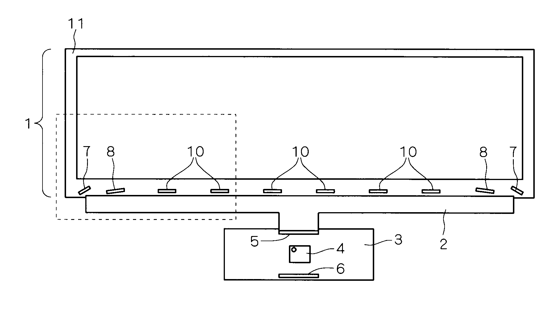
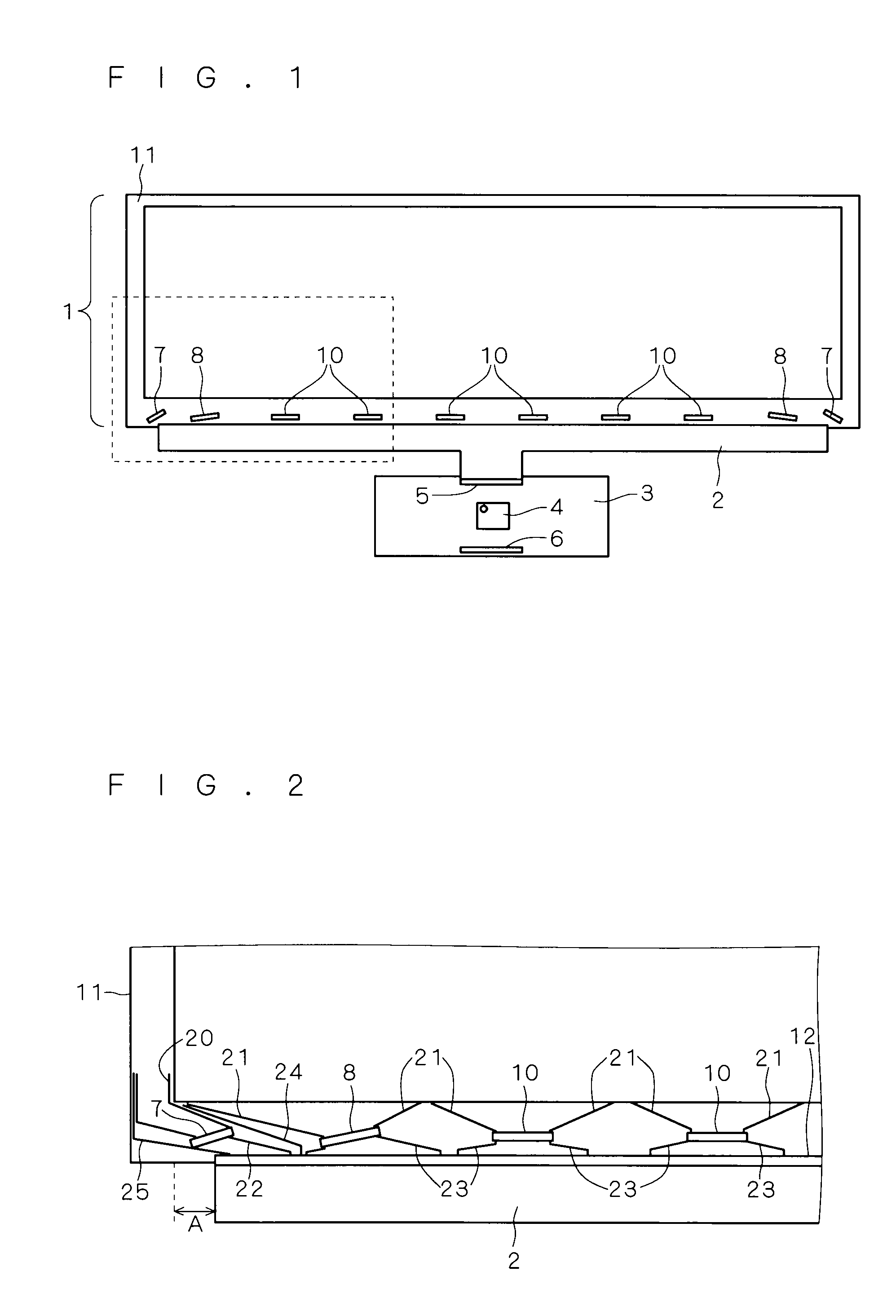
[0026]Prior to describing a liquid crystal display device of the present embodiment, a conventional liquid crystal display device will be described with reference to FIGS. 15 to 18. FIG. 15 is a front view of the conventional liquid crystal display device. As shown in FIG. 15, the conventional liquid crystal display device includes a glass substrate 11, which is an insulating substrate, a liquid crystal panel 1 including a plurality of ICs 9, 10 of COG (Chip On Glass) configuration, an FPC (Flexible Printed Circuit) 2 and a control board 3.

[0027]The plurality of ICs 9, 10 according to FIG. 15 include gate ICs 9 and source ICs 10. As shown in FIG. 15, the plurality of ICs 9, 10 are aligned on the glass substrate 11 at even intervals along a side of the glass substrate 11 which is an insulating substrate. The gate ICs 9 are arranged on both end portions of an alignment of the plurality of ICs 9, 10 while the source ICs 10 are arranged elsewhere. Respective shapes of the plurality of I...

second embodiment

[0052]FIG. 9 is a front view of a liquid crystal display device according to the present embodiment. The FPC 2 according to the present embodiment includes a plurality of FPCs 2a, 2b. As shown in FIG. 9, an FPC 2a is illustrated on the left-hand side of FIG. 9 while an FPC 2b is illustrated on the right-hand side of FIG. 9. Hereinafter, arrangements of the liquid crystal display device according to the present embodiment that are identical to those of the first embodiment will be marked with corresponding reference numerals, and arrangements which are not newly described are deemed to be identical to those of the first embodiment.

[0053]FIG. 10 is a view of a broken line portion of FIG. 9, that is, the FPC 2a illustrated on the left-hand side in FIG. 9 in an enlarged form. In the present embodiment, in each corresponding FPC 2a, 2b, specified ICs are respectively arranged to face towards central sides of the FPC 2a, 2b. In FIG. 10, a gate IC 7a and a source IC 8a, which constitute sp...

third embodiment

[0056]FIG. 12 is a front view of a liquid crystal display device according to the present invention. In the first and second embodiments, the gate ICs 7 are disposed on both end portions of the alignment of the plurality of ICs 7, 8 and 10. According to the present invention, the gate IC 7 is arranged on one end portion of the alignment of the plurality of ICs 7, 8 and 10, for instance, only on the left end portion of the alignment. In this respect, the left end portion of the alignment of the plurality of ICs 7, 8 and 10 is of identical arrangement as that of the first embodiment.

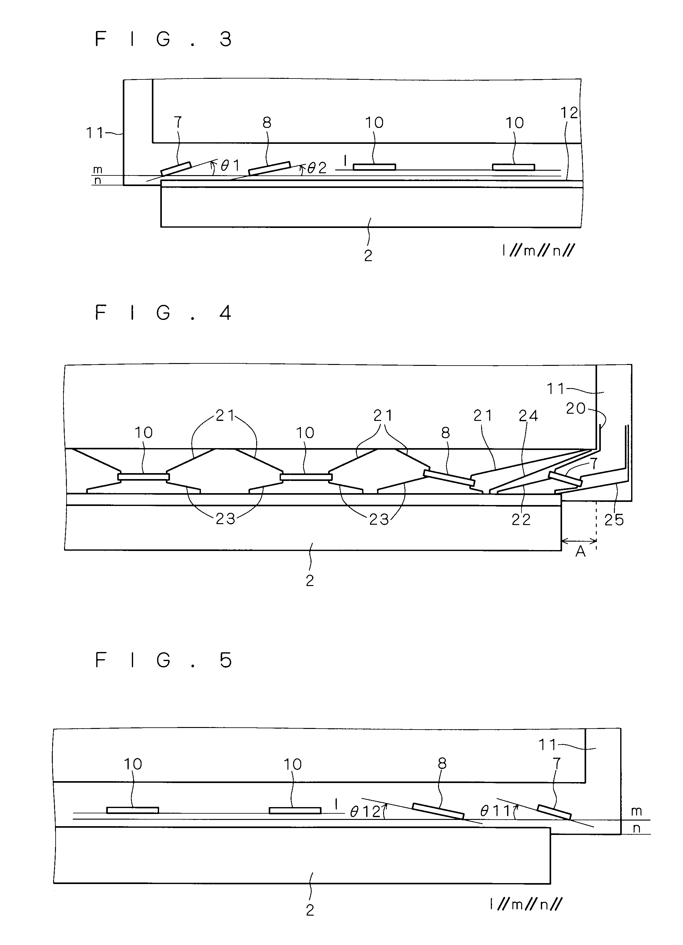
[0057]FIG. 13 is a view of a broken line portion of FIG. 12, that is, a right-hand side of the FPC 2 shown in an enlarged form. According to the present embodiment, specified ICs from among the plurality of ICs 7, 8 and 10 are identical to those of the first embodiment in a point that they are arranged in that extending directions of longer sides thereof are inclined with respect to an extending direction ...


PUM


Abstract

An object of the present invention is to reduce a lateral width of an FPC also with evenly aligned and arranged plurality of ICs. The liquid crystal display device according to the present invention includes a glass substrate, a plurality of ICs of COG (Chip On Glass) configuration aligned on a glass substrate along a side thereof, and an FPC (Flexible Printed Circuit) that is arranged to extend along the side of the glass substrate and that is connected to the plurality of ICs. Specified ICs from among the plurality of ICs are arranged in that extending directions of their longer sides are inclined with respect to an extending direction of the side of the glass substrate such that the longer sides face towards a central side of the FPC.

Description

BACKGROUND OF THE INVENTION[0001]1. Field of the Invention[0002]The present invention relates to a liquid crystal display device, and particularly to a liquid crystal display device having ICs of COG (Chip On Glass) configuration mounted thereon.[0003]2. Description of the Background Art[0004]A liquid crystal display employs a COG (Chip On Glass) technique in these years. In a liquid display panel of the liquid crystal display, ICs of COG configuration aligned on a glass substrate, which is an insulating substrate, are connected to a control board via an FPC (Flexible Printed Circuit). Japanese Patent Application Laid-Open No. 2000-137445 discloses a flat display device employing such an FPC. In a case the glass substrate of the liquid crystal display is laterally long, a lateral width of the FPC will become accordingly long so that it is required to reduce a cumulative dimensional tolerance of panel connecting terminals of the FPC. In dealing with this matter, it has been suggested...

Claims


Application Information

Patent Timeline
IPC IPC(8): G02F1/1345
CPCH05K1/147G02F1/13452
Inventor TASHIRO, TOMOHIRO
Owner TRIVALE TECH
Why Eureka
Try Eureka