
Method and apparatus for measuring 3-dimensional position and orientation of reflective mirror package

a reflective mirror and position measurement technology, applied in measurement devices, instruments, television systems, etc., can solve the problems of large height difference, inability to precisely measure dimensional errors, and white light reflected from objects generating interference patterns on image sensors, etc., to achieve convenient use and reduce measurement time

Inactive Publication Date: 2009-06-18
SAMSUNG ELECTRO MECHANICS CO LTD
View PDF4 Cites 10 Cited by
  • Summary
  • Abstract
  • Description
  • Claims
  • Application Information

AI Technical Summary

Benefits of technology

[0010]The present invention provides a method and an apparatus for simultaneously measuring a 3D position and an orientation of an object, which can reduce a measurement time and be easily employed to measure various objects.

Problems solved by technology

However, since assembling errors arises due to dimensional errors of diverse elements, such dimensional errors should be precisely measured.
According to the method, white light reflected from an object generates interference patterns on the image sensor.
In addition, when the size of the object is 4 mm or more, if a lens having low magnifying power is used, a great height difference is generated due to an initial error generated due to a tilt angle.
Thus, it is difficult to form the interference patterns.
However, when another object having a size different from that of a previously measured object is measured, it is difficult to calibrate the image sensor.
Otherwise, it is difficult to distinguish the tilt angles (α, β) and the height of the object since a height error affects the tilt angles (α, β).
However, when the base line and the object are not on the same plane, since the depth of focus is reduced, it is difficult to simultaneously measure the tilt angle and the height of the object.

Method used


Image

  • Method and apparatus for measuring 3-dimensional position and orientation of reflective mirror package
  • Method and apparatus for measuring 3-dimensional position and orientation of reflective mirror package
  • Method and apparatus for measuring 3-dimensional position and orientation of reflective mirror package

Examples


Embodiment Construction

[0019]Hereinafter, the present invention will be described in detail by explaining exemplary embodiments of the invention with reference to the attached drawings.

[0020]FIG. 1 is a structural view of an apparatus for measuring a 3D position and an orientation of an object according to an exemplary embodiment of the present invention.

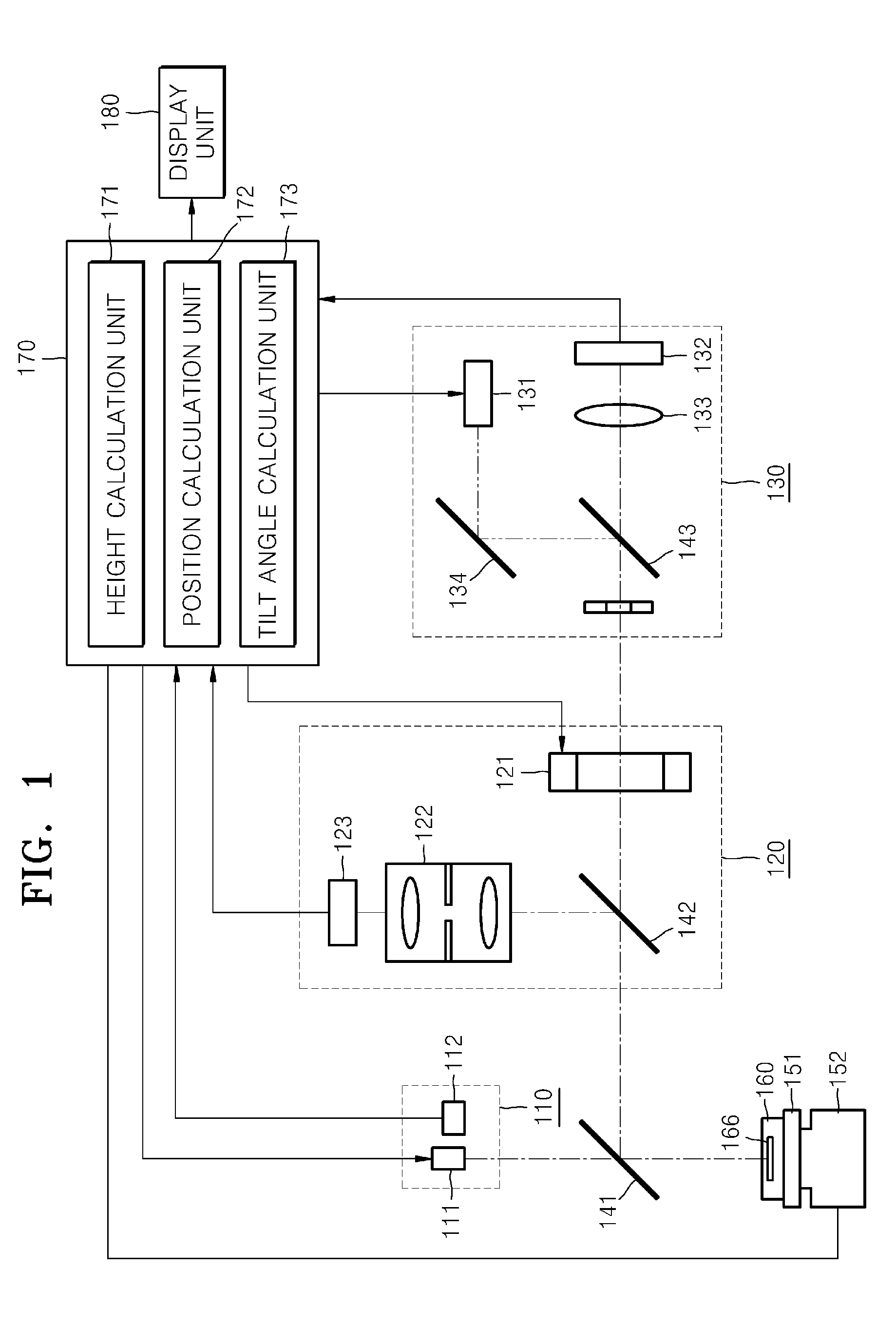
[0021]Referring to FIG. 1, the apparatus includes a height measurement unit 110, a position measurement unit 120, a tilt angle measurement unit 130, a controlling unit 170, and a display unit 180.

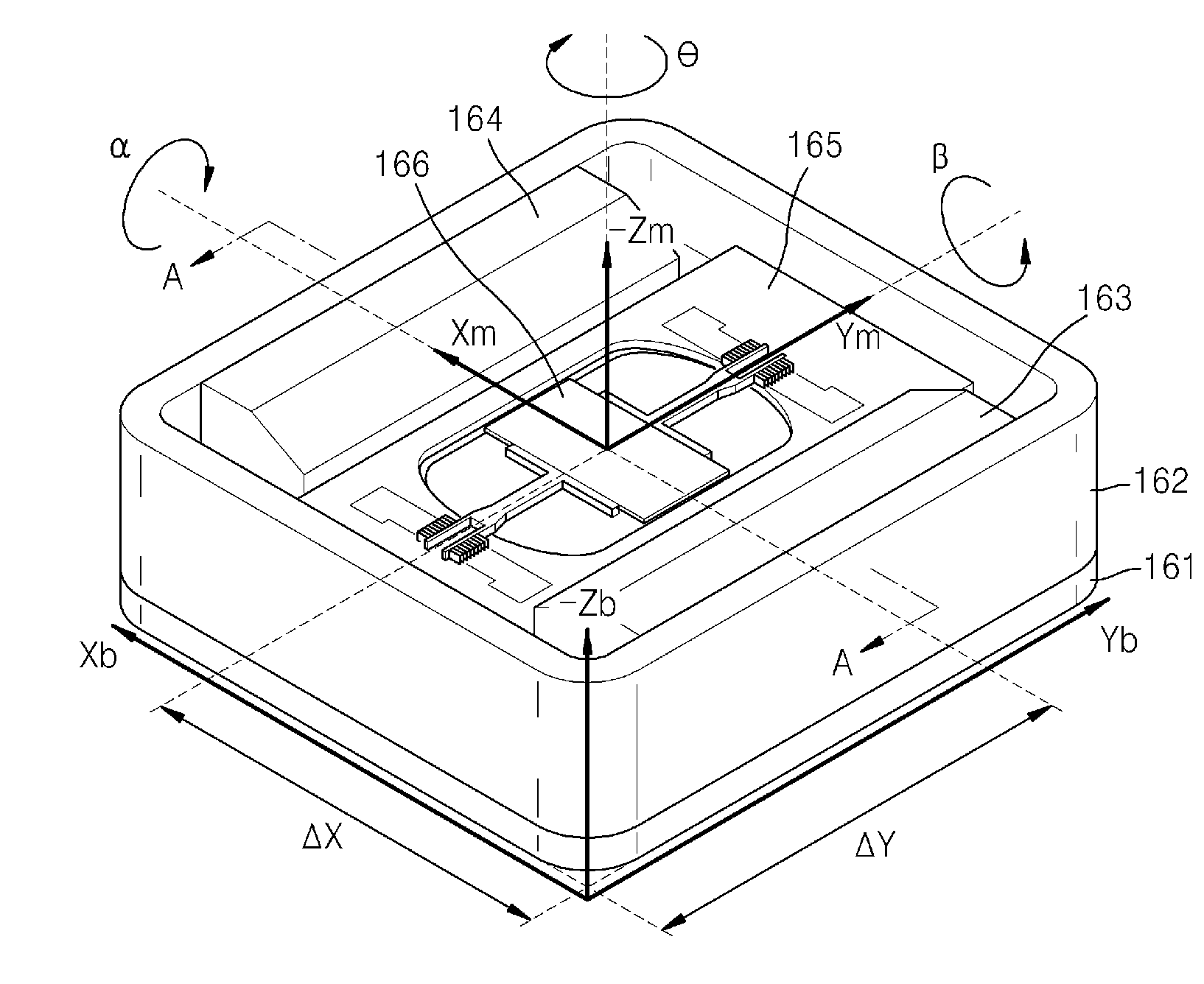
[0022]An object 160, such as a reflective mirror package, is mounted on a stage 151. The stage 151 is moved accurately along six axes by a stage driving unit 152 disposed below the stage 151.

[0023]The height measurement unit 110, the position measurement unit 120, and the tilt angle measurement unit 130 constitute a coaxial optical system in conjunction with first through third semi transparent mirrors 141, 142 and 143. In this regard, when the object 160 is moun...


PUM


Abstract

Provided are a method and an apparatus for measuring a 3-dimensional (3D) position and an orientation of an object. The apparatus includes: a height measurement unit including a first light source and a first image sensor receiving light that is emitted from the first light source to the object and reflected from the object; a position measurement unit including a second light source, and a second image sensor receiving light that is emitted from the second light source to the object and reflected from the object; a tilt angle measurement unit including a third light source and a third image sensor receiving light that is emitted from the third light source to the object and reflected from the object; and a controlling unit selectively powering on or off the first, second, and third light sensors, and calculating a height variation, a position variation and tilt angles of the object by using images that are respectively formed on the first, second, and third image sensors.

Description

CROSS-REFERENCE TO RELATED PATENT APPLICATION[0001]This application claims priority from Korean Patent Application No. 10-2007-0129107, filed on Dec. 12, 2007 in the Korean Intellectual Property Office, the disclosure of which is incorporated herein in its entirety by reference.BACKGROUND OF THE INVENTION[0002]1. Field of the Invention[0003]Methods and apparatuses consistent with the present invention relate to measuring a three-dimensional (3D) position and an orientation of an object, and more particularly, to measuring a 3D position and orientation of a reflective mirror package of a scanner device.[0004]2. Description of the Related Art[0005]A scanner device includes a reflective mirror for deflecting a laser beam. The reflective mirror is assembled together with a magnet, a yoke, and a base plate so as to constitute a reflective mirror package. The reflective mirror must be precisely assembled to be perpendicular to the magnet so that the reflective mirror can be correctly driv...

Claims


Application Information

Patent Timeline
IPC IPC(8): G01B11/00
CPCG01B11/272G01B11/0608H04N17/02
Inventor CHO, YONG-CHULCHANG, SEOK-MO
Owner SAMSUNG ELECTRO MECHANICS CO LTD
Features
  • Generate Ideas
  • Intellectual Property
  • Life Sciences
  • Materials
  • Tech Scout
  • Unparalleled Data Quality
  • Higher Quality Content
  • 60% Fewer Hallucinations
Learn More