Optically coupled device and optical module including optically coupled device

a technology of optical coupling and optical module, which is applied in the direction of optics, optical light guides, instruments, etc., can solve the problems of limited optical coupling efficiency, and insufficient positioning accuracy that is difficult to achieve by only mechanical operation, so as to reduce manufacturing costs, improve productivity, and facilitate and appropriately position the effect of photoelectric conversion devices

Active Publication Date: 2009-06-18
ENPLAS CORP
View PDF2 Cites 34 Cited by
  • Summary
  • Abstract
  • Description
  • Claims
  • Application Information

AI Technical Summary

Benefits of technology

[0037]In the invention, a photoelectric conversion device can be easily and appropriately positioned. Moreover, reduction in manufacturing costs and improvement in productivity can be achieved.

Problems solved by technology

However, because a photoelectric conversion device positioning mechanism for positioning the photoelectric conversion device in relation to the optically coupled device has not been standardized, sufficient positioning accuracy is difficult to achieve by only a mechanical operation.
When the active alignment is performed, a certain amount of error is permitted regarding alignment in the emission or irradiation direction of light in the light-emitting unit or the light-receiving unit of the photoelectric conversion device, because the error has little effect on optical coupling efficiency.
However, alignment in a direction perpendicular to the emission or irradiation direction of the light in the light-emitting unit or the light-receiving unit is required to be particularly precise, because an error has a significant effect on optical coupling efficiency.
Therefore, conventionally, appropriate positioning of the photoelectric conversion device to achieve sufficient optical coupling efficiency could not be easily performed.

Method used


Image

  • Optically coupled device and optical module including optically coupled device
  • Optically coupled device and optical module including optically coupled device
  • Optically coupled device and optical module including optically coupled device

Examples


first embodiment

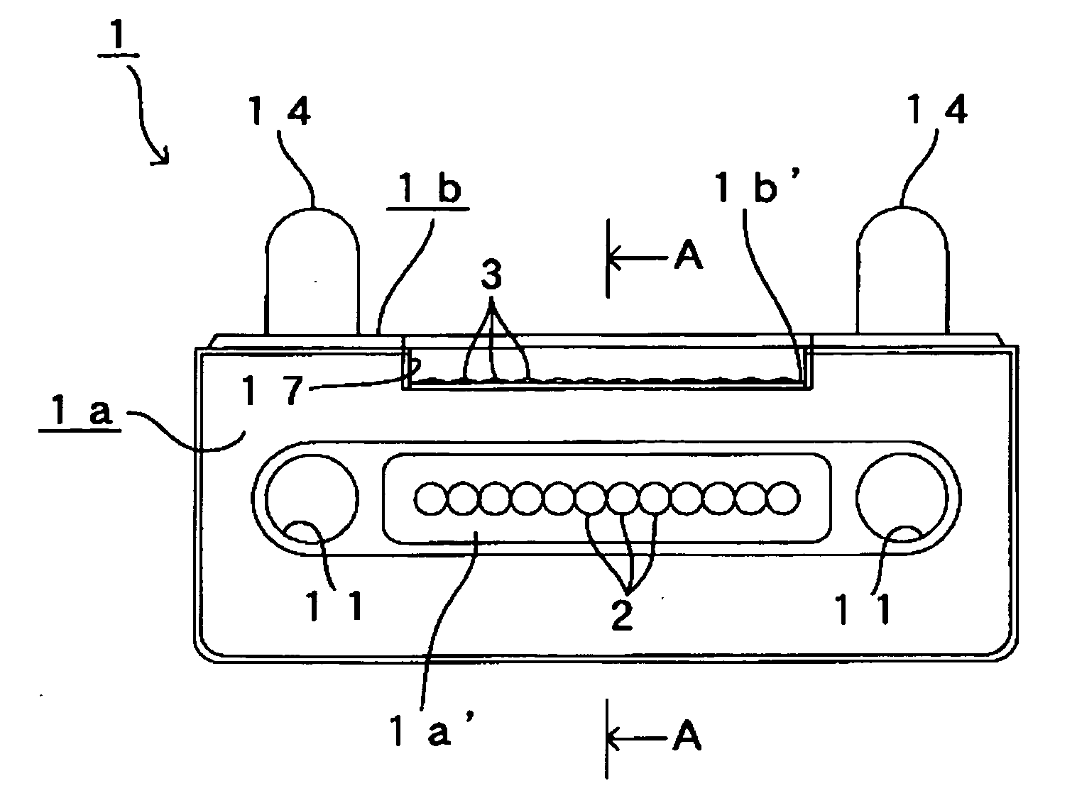
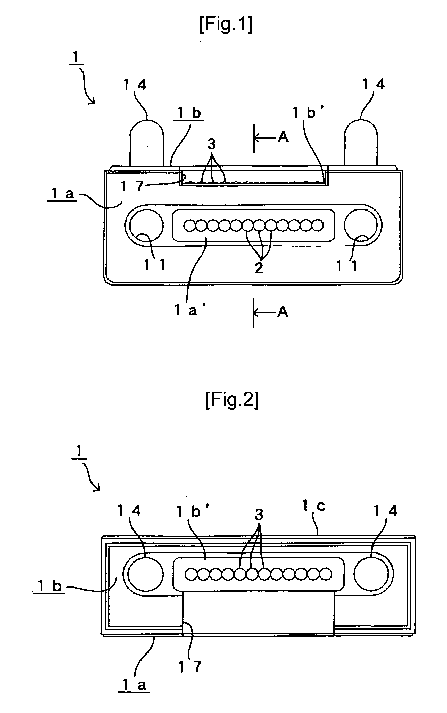
[0053]An optically coupled device and an optical module according to a first embodiment of the present invention will be described below with reference to FIG. 1 to FIG. 8.

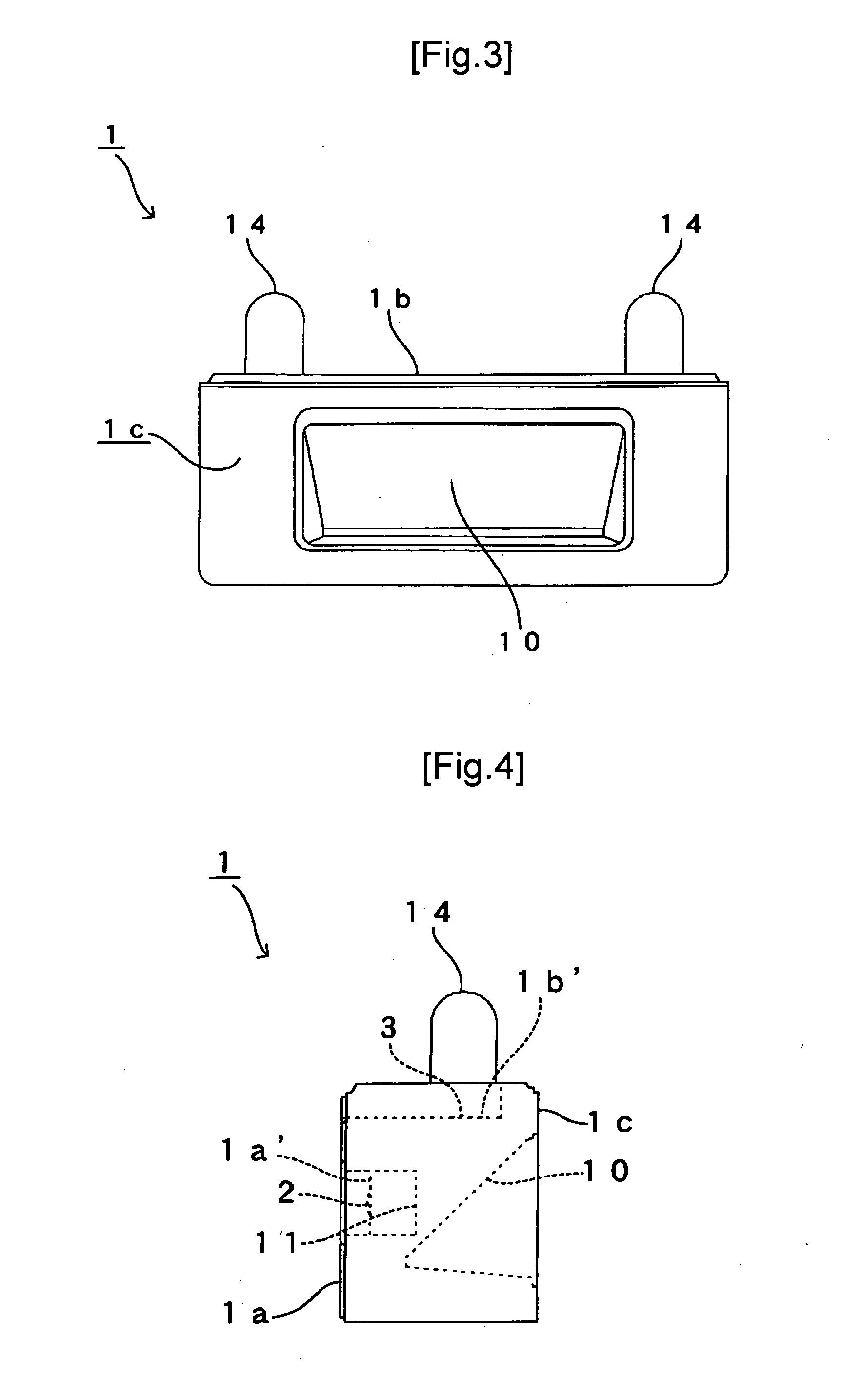
[0054]FIG. 1 is a front view of an optically coupled device 1 according to the first embodiment. FIG. 2 is a planar view of FIG. 1. FIG. 3 is a rear view of FIG. 1. FIG. 4 is a right-side view of FIG. 1. FIG. 5 is a cross-sectional view taken along line A-A in FIG. 1. FIG. 6 is an exploded right-side view of an optical module 4 according to the first embodiment.

[0055]The optically coupled device 1 according to the first embodiment is formed in a manner allowing each of a plurality of photoelectric conversion elements formed on a photoelectric conversion device and respective end surfaces of a plurality of multi-mode optical fibers corresponding to the photoelectric conversion elements to be optically coupled. The photoelectric conversion elements emit or receive light.

[0056]In other words, as shown in FIG. 1 to FI...

second embodiment

[0094]Next, an optically coupled device and an optical module according to a second embodiment of the present invention will be described with reference to FIG. 9.

[0095]Parts of the basic configuration that are the same or similar to those according to the first embodiment are given the same reference numbers and described.

[0096]A basic configuration of the optically coupled device 1 according to the second embodiment is similar to that according to the first embodiment. However, the optically coupled device 1 according to the second embodiment differs from that according to the first embodiment in that dimensional accuracy is more relaxed, thereby improving manufacturability. On the other hand, the optically coupled device 1 according to the second embodiment is designed to minimize labor involved with alignment should alignment of the photoelectric conversion device be required.

[0097]In other words, in the optically coupled device 1 according to the second embodiment, with the VCS...


PUM


Abstract

An optically coupled device and an optical module including the optically coupled device are provided in which a photoelectric conversion device can be easily and appropriately positioned, and reduction in manufacturing costs and improvement in productivity can be achieved.A configuration is made in which, when a photoelectric conversion device 7 is attached to an optically coupled device 1, sufficient optical coupling efficiency can be achieved simply by a mechanical operation in which a photoelectric conversion device 7-side positioning mechanism 12 is engaged with an optically coupled device 1-side positioning mechanism 11, without requiring alignment in any of an emission or irradiation direction of light in a photoelectric conversion element 5 and a direction perpendicular thereto.

Description

BACKGROUND OF THE INVENTION[0001]1. Field of the Invention[0002]The present invention relates to an optically coupled device and an optical module including the optically coupled device. In particular, the present invention relates to an optically coupled device and an optical module including the optically coupled device suitable for optically coupling a photoelectric conversion device and a multi-mode optical fiber.[0003]2. Description of the Related Art[0004]In recent years, with increasing speed and capacity of data communication, the need is further rising for an optical fiber communication technology using an optical fiber.[0005]An optical fiber communication technology such as this uses an optically coupled device to which an optical fiber and a photoelectric conversion device (such as a semiconductor laser or a photodetector) are attached. In many optically coupled devices, a surface facing a photoelectric conversion element (light-emitting unit or light-receiving unit) of t...

Claims


Application Information

Patent Timeline
Patent Type & Authority Applications(United States)
IPC IPC(8): G02B6/26
CPCG02B6/4292G02B6/4204
Inventor MORIOKA, SHIMPEI
Owner ENPLAS CORP
Why Eureka
Try Eureka