

Developing device and image forming apparatus
- Summary
- Abstract
- Description
- Claims
- Application Information
AI Technical Summary
Benefits of technology
Problems solved by technology
Method used
Image

Examples
first embodiment
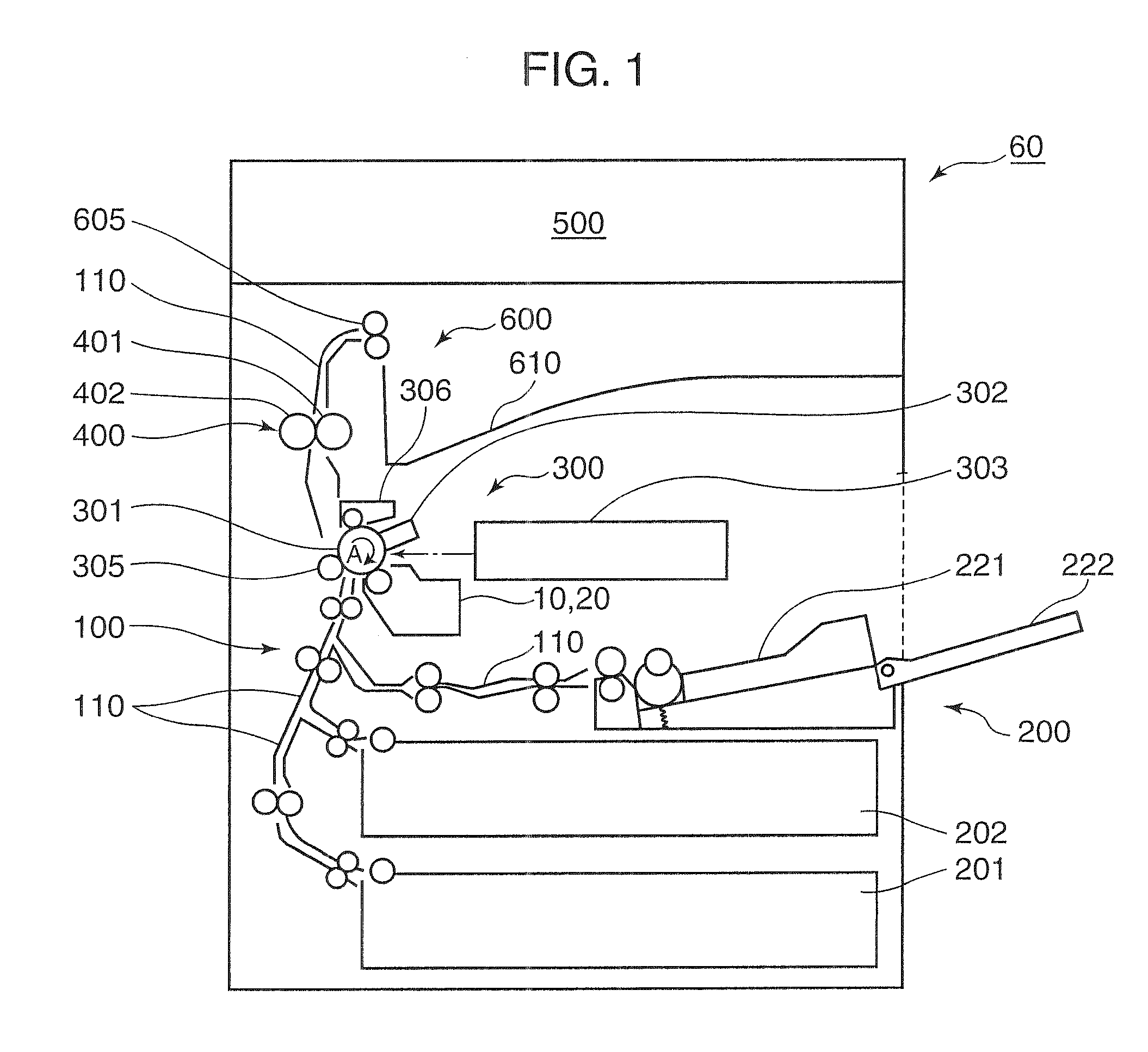
[0037]FIG. 1 is a schematic view illustrating the configuration of an image forming apparatus (copying machine) 60 having a developing device in an embodiment of the present invention. The copying machine 60 is a so-called internally paper-feeding copying machine having a paper-feeding unit 200 disposed in the lower region of a copying machine main body, an image forming unit 300 disposed above the paper-feeding unit 200, a fixing unit 400 disposed downstream of the image forming unit 300, an image-reading unit 500 disposed in the upper region of the copying machine main body, and a paper discharge unit 600 disposed between the copying machine main body and the image-reading unit 500. The copying machine main body has a paper-conveying unit 100 for connection of the paper-feeding unit 200, the image forming unit 300, the fixing unit 400, and the paper discharge unit 600.
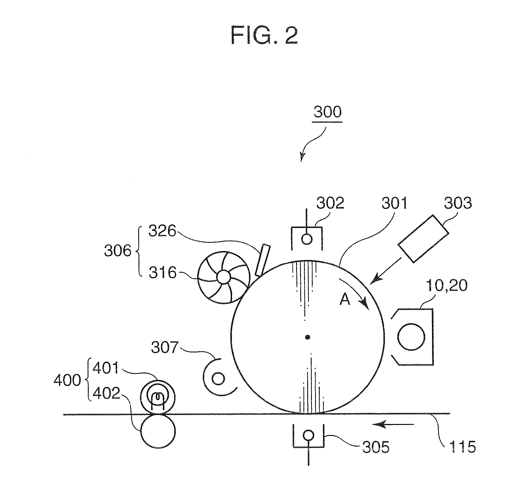
[0038]The image forming unit 300, which forms a particular toner image on paper by electrophotography process, has...
second embodiment
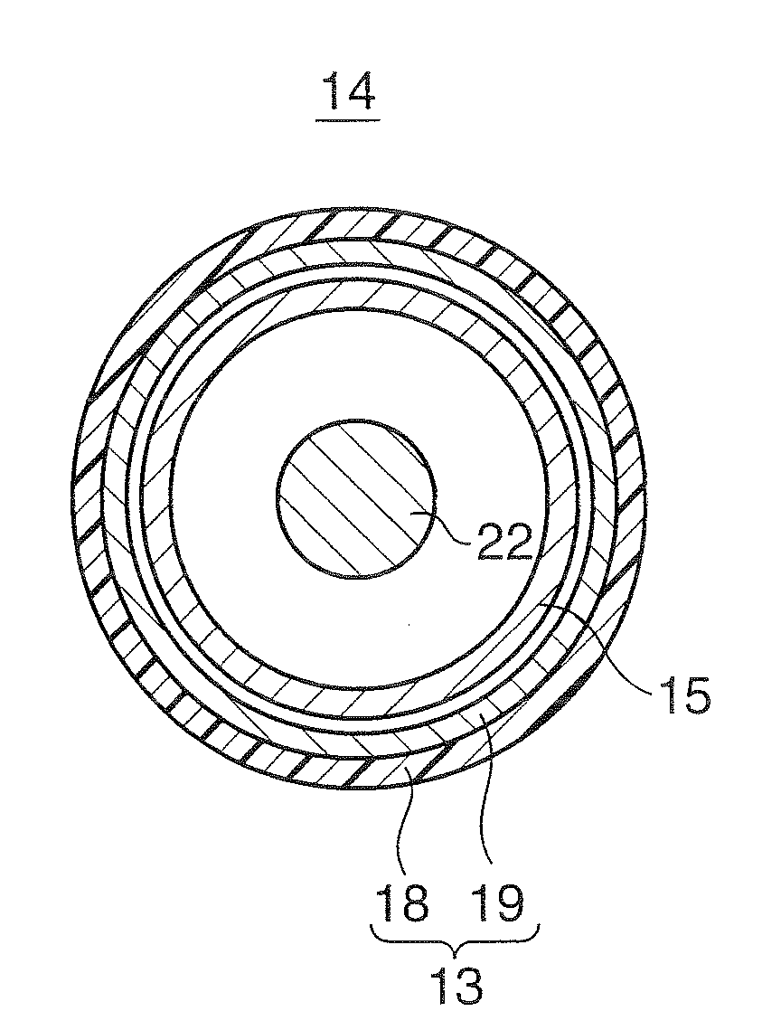
[0072]Hereinafter, the development device 20 in the second embodiment having a configuration modified from that of the developing device 10 in the first embodiment of the present invention, as shown in FIG. 7. FIG. 7 is a schematic cross-sectional view illustrating the developing unit (developing device) 20 described above, together with a photosensitive drum 301.
[0073]The developing device 20 is a developing device in the touchdown development process, and has, for example, a developing roller 61, a magnetic roller 62, agitating members 63 and 64, and a blade 65.
[0074]The agitating members 63 and 64 have helical blades, which charge the toner of the two-component developer, while conveying and agitating the two-component developer in the mutually opposite directions. The agitating member 63 supplies the two-component developer including the charged toner and the carrier to the magnetic roller 62.
[0075]The magnetic roller 62 conveys the two-component developer by attracting the two-...
examples
[0082]Hereinafter, an example of the developing device 20 in the second embodiment will be described.
[0083]The copying machine used in Examples and Comparative Examples is a conventional copying machine (KM-C3232, manufactured by Kyocera Mita Corp.) with its developing roller of developing device replaced with the following developing roller. In Examples 1 to 7 and Comparative Examples 2 to 4, the replaced developing roller is a developing roller having a resin layer on the surface shown in FIG. 5A, while in Comparative Example 1, it is a developing roller surface-treated with alumite.
[0084]The developing roller in Example 1 is prepared in the following manner:
[Preparation of Urethane Resin (A)]
[0085]First, a urethane resin (A) was prepared.
[0086]Specifically, 110 g (OH group: 0.074 mol) of a polyether diol having a vinyl group on the side chain represented by the following Formula (1) (molecular mass: 3000, n: m: o=30: 50: 20), 9.0 g (NCO group: 0.072 mol) of 4,4′-diphenylmethane d...
PUM
 Abstract
Description
Claims
Application Information