Catheter having transitioning shaft segments

a technology of transitioning shaft and catheter, which is applied in the field of catheters, can solve the problems of serious harm or death to patients, and achieve the effects of improving tip pull strength, low profile, and gradual change of bending stiffness

Active Publication Date: 2009-06-18
ABBOTT CARDIOVASCULAR
View PDF108 Cites 67 Cited by
  • Summary
  • Abstract
  • Description
  • Claims
  • Application Information

AI Technical Summary

Benefits of technology

[0008]In one embodiment, a balloon catheter of the invention has a distal tip member and a coupling band member surrounding a junction of the shaft inner tubular member, and has a gradual change in bending stiffness along a distal end section of the shaft which extends distally from a location within the balloon interior. Specifically, the balloon catheter has a distal tip member which is secured to a distal end of the inner tubular member (i.e., the portion of the shaft extending in the balloon interior) to define a distal end section of the shaft lumen, and a distal coupling band member on an outer surface of the inner tubular member surrounding a junction of the inner tubular membe...

Problems solved by technology

One difficultly has been providing a flexibility transition which improves catheter maneuverability, yet with a sufficiently strong transition bond, especially at the transition between the distal end of the shaft inner tubular member (extending through the balloon interior) an...

Method used


Image

  • Catheter having transitioning shaft segments
  • Catheter having transitioning shaft segments
  • Catheter having transitioning shaft segments

Examples


Embodiment Construction

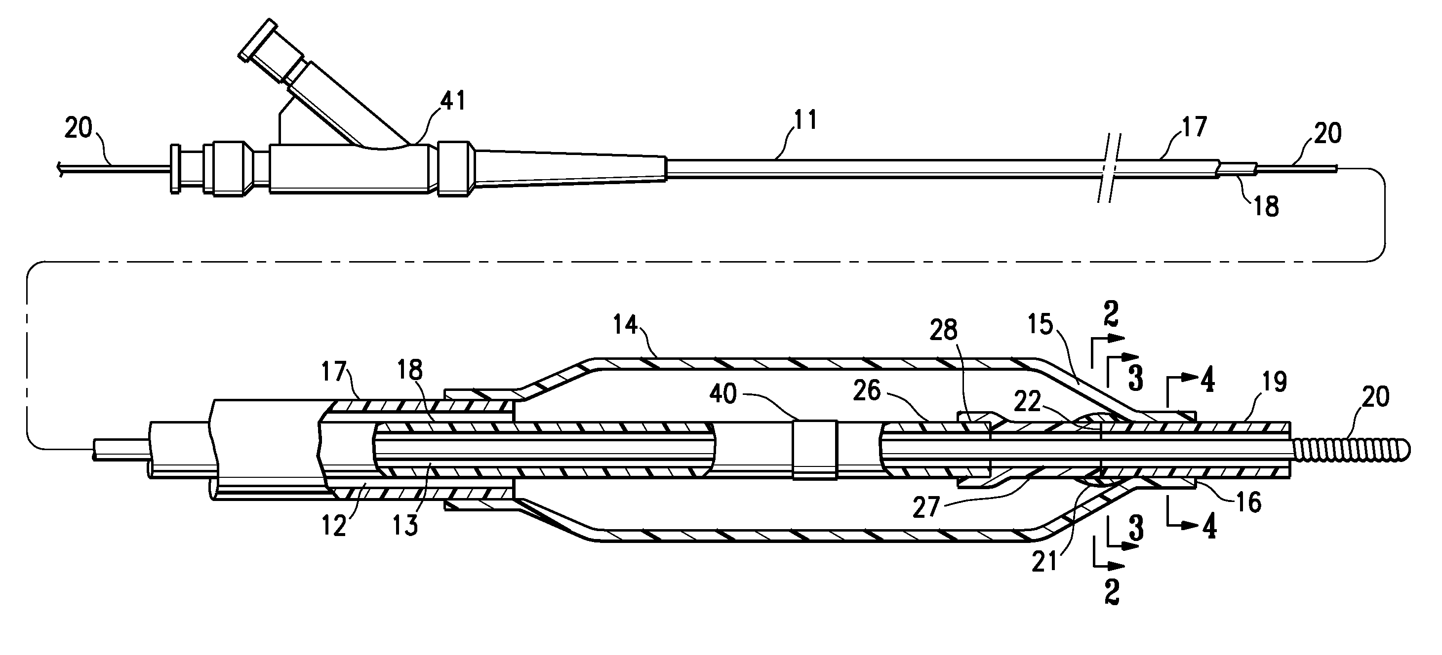
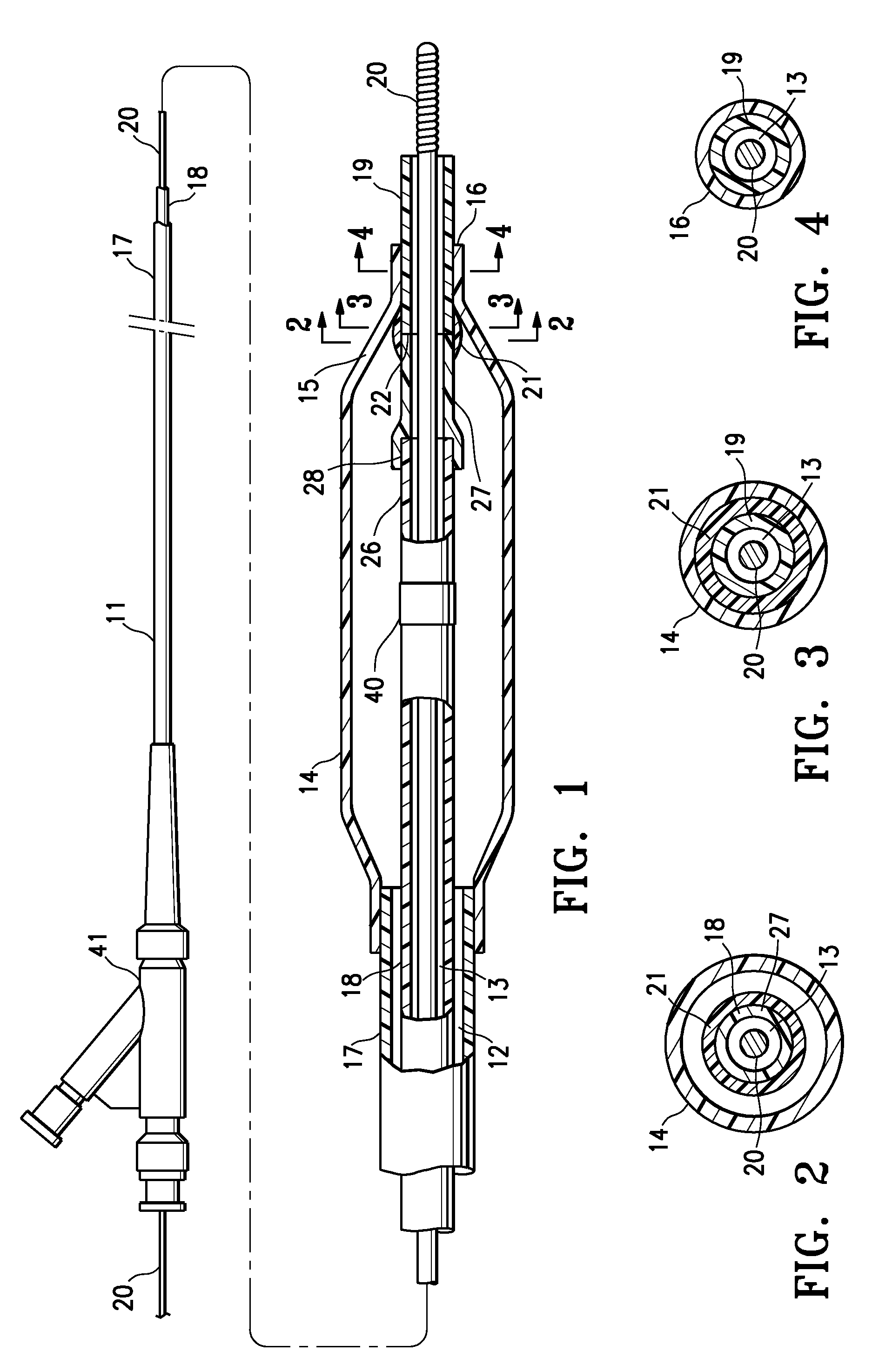
[0022]FIG. 1 illustrates an elevational view, partially in section, of a balloon catheter 10 embodying features of the invention, generally comprising an elongated shaft 11 having a proximal end, a distal end, an inflation lumen 12, a guidewire receiving lumen 13, and a balloon 14 on a distal shaft section having an inflatable working length between an inflatable proximal cone section and an inflatable distal cone section 15, and a proximal skirt section and distal skirt section 16 sealingly secured to the shaft, such that an interior of the balloon is in fluid communication with the inflation lumen 12. In the illustrated embodiment the shaft 11 comprises an outer tubular member 17 with the inflation lumen 12 therein, and an inner tubular member 18 with the guidewire lumen 13 therein, and a distal tip member 19 is secured to a distal end of the inner tubular member 18 to define a distal end section of the guidewire lumen. A radiopaque marker band 40 of metal or radiopaque loaded pol...


PUM

PropertyMeasurementUnit
Lengthaaaaaaaaaa
Diameteraaaaaaaaaa
Flexibilityaaaaaaaaaa

Abstract

A catheter having shaft segments which are joined together by a strong bond providing a low profile shaft section with a flexibility transition and/or a compositional transition. A balloon catheter embodying features of the invention has a distal tip member and a coupling band member surrounding a junction of an inner tubular member of the shaft, and has a gradual change in bending stiffness along a distal end section of the shaft which extends distally from a location within the balloon interior. Another catheter embodying features of the invention has shaft segments joined together by a diagonal seam.

Description

CROSS-REFERENCES TO RELATED APPLICATIONS[0001]NoneBACKGROUND OF THE INVENTION[0002]This invention generally relates to catheters, and particularly intravascular catheters for use in percutaneous transluminal coronary angioplasty (PTCA) or for the delivery of stents.[0003]In percutaneous transluminal coronary angioplasty (PTCA) procedures, a guiding catheter is advanced in the patient's vasculature until the distal tip of the guiding catheter is seated in the ostium of a desired coronary artery. A guidewire is first advanced out of the distal end of the guiding catheter into the patient's coronary artery until the distal end of the guidewire crosses a lesion to be dilated. A dilatation catheter, having an inflatable balloon on the distal portion thereof, is advanced into the patient's coronary anatomy over the previously introduced guidewire until the balloon of the dilatation catheter is properly positioned across the lesion. Once properly positioned, the dilatation balloon is infla...

Claims


Application Information

Patent Timeline
IPC IPC(8): A61M25/10A61M25/01A61F2/958
CPCA61M25/0054A61M25/0069A61M25/1006A61M25/1034A61M2025/1061A61M2025/1093A61M25/104A61M25/1027A61M2205/32B29C65/48B29C66/10B29L2031/7543
Inventor ARANA, RAMONBROWN, DANIELNOVAK, CURT A.MANN, JUSTIN K.SIMPSON, JOHN A.WILSON, BRUCE M.BARBOD, LEONARD D.
Owner ABBOTT CARDIOVASCULAR
Why Eureka
Try Eureka