Installation tool and correction tool for helical coil insert

Inactive Publication Date: 2009-06-25
HONDA MOTOR CO LTD
View PDF14 Cites 7 Cited by
  • Summary
  • Abstract
  • Description
  • Claims
  • Application Information

AI Technical Summary

Benefits of technology

[0018]If the first winding of the helical coil insert separates from the internally threaded part, the helical coil insert does not need to be replaced with a new insert because the first winding can be returned to the internally threaded part by the hook. Therefore, the helical coil insert can be used effectively.
[0020]When the first winding of the helical coil insert has separated from the internally threaded part, the first winding often rests on the crest of the internally threaded part. When the portion resting on the crest is subjected to an impact, this portion easily fits into the recession of the internally threaded part. Specifically, the helical coil insert can be easily corrected by creating a force of impact with the cylindrical weight.
[0021]In a preferred form, the hook comprises a groove formed by cutting out a part of the tool shaft. Since there is no need to prepare new material to form the groove, the cost of the helical coil insert installation tool can be reduced.
[0024]The helical coil insert correction tool is a simple tool having merely a hook provided to a rod-shaped tool shaft. Since the structure is simple, the cost of the helical coil insert correction tool can be reduced.
[0026]When the first winding of the helical coil insert has separated from the internally threaded part, the first winding rests on the crest of the internally threaded part. When this portion is subjected to impact, this portion easily fits into the recession of the internally threaded part. Specifically, the helical coil insert can be easily corrected by creating a force of impact with the cylindrical weight.

Problems solved by technology

It is difficult to regulate this force.
The helical coil insert then becomes useless and replacement costs are incurred.

Method used


Image

  • Installation tool and correction tool for helical coil insert
  • Installation tool and correction tool for helical coil insert
  • Installation tool and correction tool for helical coil insert

Examples


Embodiment Construction

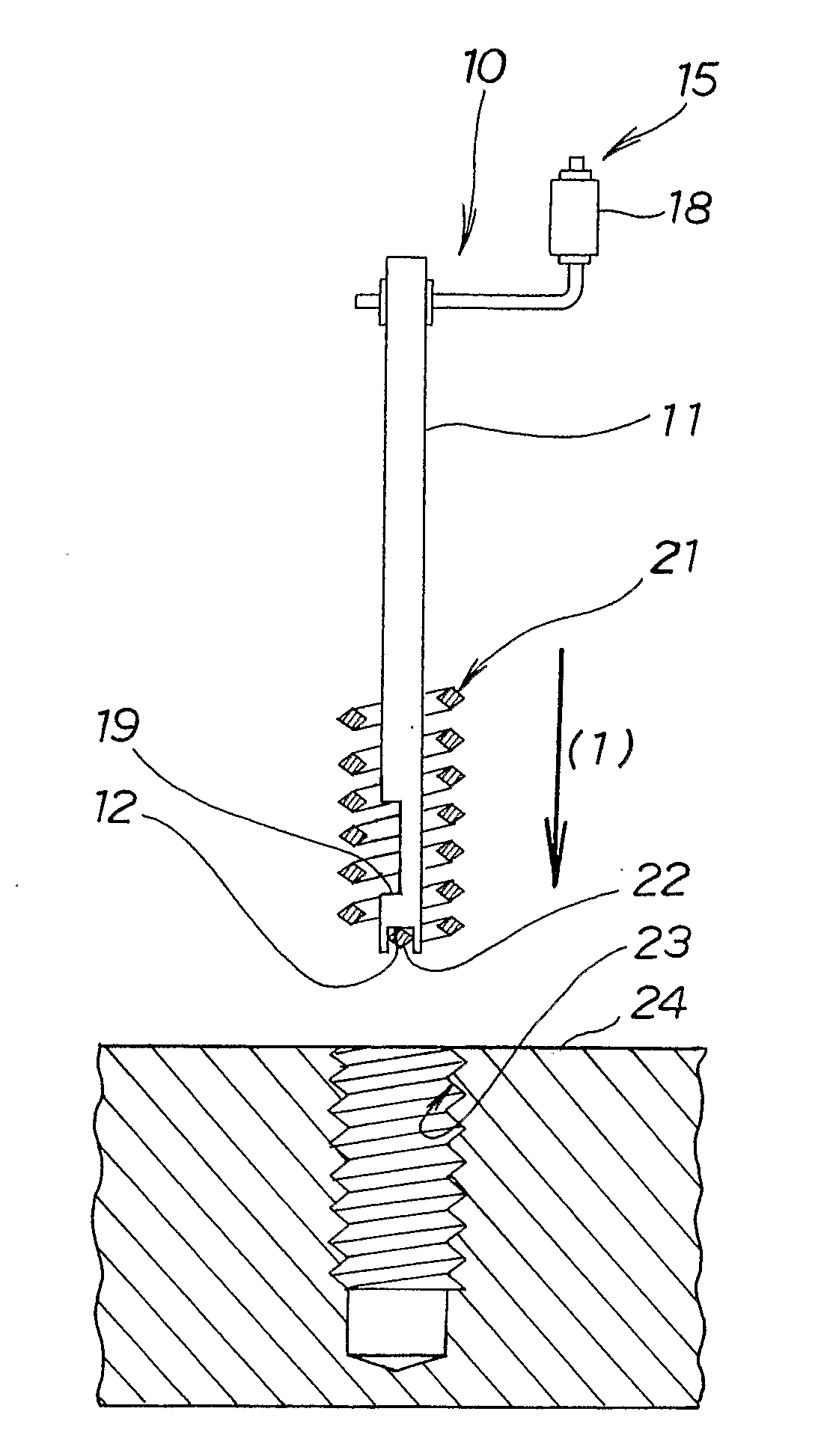
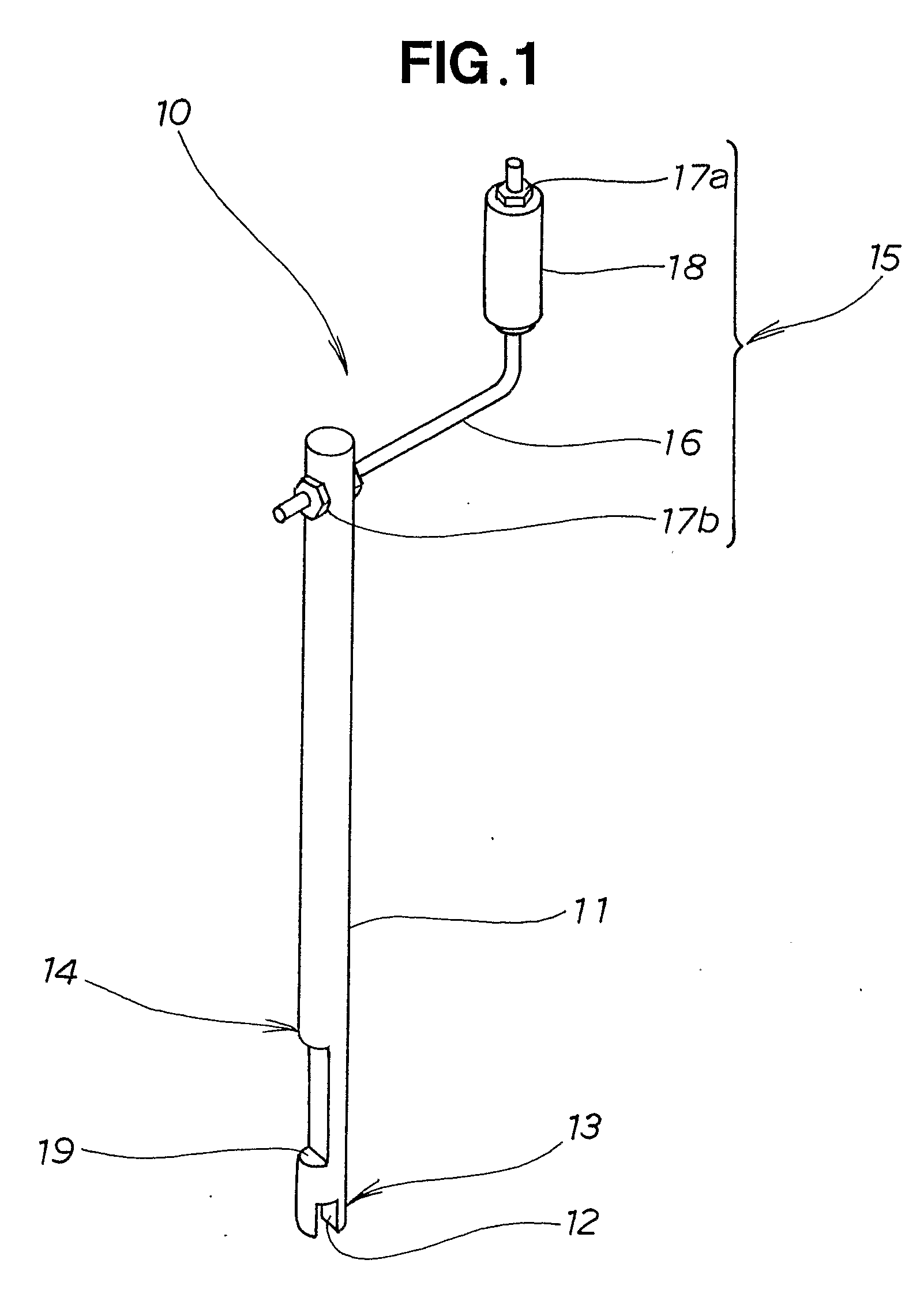
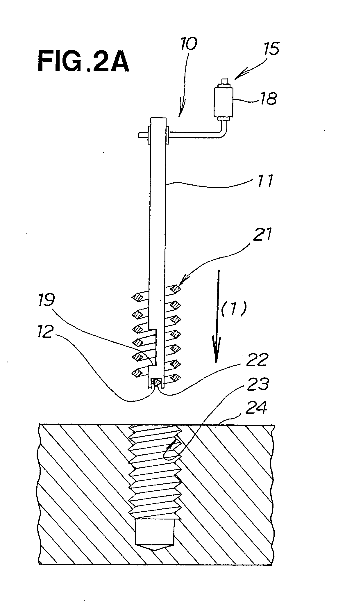
[0044]In FIG. 1, a helical coil insert installation tool 10 is composed of a rod-shaped tool shaft 11, a tang pincer 13 formed at one end of the tool shaft 11 and provided with a tang groove 12 for pinching the tang when the helical coil insert is threadably inserted into the internally threaded part or when the tang is folded over, a hook 14 that is formed in the tool shaft 11 and that hooks onto one end of the helical coil insert, and a handle 15 that is provided to the other end of the tool shaft 11 and that turns the tool shaft 11 when the helical coil insert is threadably inserted into the internally threaded part.

[0045]The handle 15 is composed of an L-shaped handle shaft 16, a handle grip 18 that can be grasped by an operator, a nut 17a for fixing the handle grip 18 to the handle shaft 16, and a nut 17b for fixing one end of the handle shaft 16 to the tool shaft 11.

[0046]The hook 14 is, e.g., a groove 19 formed by cutting out a part of the tool shaft 11.

[0047]The following is...


PUM


Abstract

An installation tool is used when a helical coil insert having a diamond-shaped cross section is inserted into an internally threaded part. The installation tool (10) has a rod-shaped tool shaft (11). The tool shaft (11) has a tang pincer (13) for threadably inserting a helical coil insert (21) into an internally threaded part (23) and bending a tang (22).

Description

TECHNICAL FIELD[0001]The present invention relates to an installation tool used when a helical coil insert of diamond-shaped cross section is inserted into an internally threaded part, as well as to a correction tool used when the installed helical coil insert is corrected.BACKGROUND ART[0002]When a steel bolt is threadably inserted into an internally threaded part (female thread part) formed in a member made of aluminum or another such soft material, the internally threaded part sometimes deforms.[0003]One corrective measure is to form an internally threaded part with a somewhat large diameter in the soft material, to insert a steel helical coil insert having a diamond-shaped cross section into the internally threaded part, and to form a new internally threaded part using this helical coil insert. Since the helical coil insert is made of steel, the new thread is more rigid and deformation is not a concern.[0004]Helical coil inserts are formed by winding a steel wire having a diamon...

Claims


Application Information

Patent Timeline
IPC IPC(8): B23P19/04
CPCY10T29/53691B25B27/143
Inventor YUI, TSUTOMU
Owner HONDA MOTOR CO LTD
Why Eureka
Try Eureka