Delay interferometer

Inactive Publication Date: 2009-12-10
YOKOGAWA ELECTRIC CORP
View PDF39 Cites 4 Cited by
  • Summary
  • Abstract
  • Description
  • Claims
  • Application Information

AI Technical Summary

Benefits of technology

[0008]Exemplary embodiments of the present invention provide a delay interferometer in which the difference of optical path lengths to output ports in the delay interferometer can be easily corrected.

Problems solved by technology

When it is assumed that the optical detector 122 is an optical fiber, axis and angle deviations in the optical axis are produced in the mirror 116 or 117 by position and angle errors of the mirror surface, thereby producing a problem in that the coupling to the optical fiber is hardly performed.

Method used


Image

  • Delay interferometer
  • Delay interferometer
  • Delay interferometer

Examples


Embodiment Construction

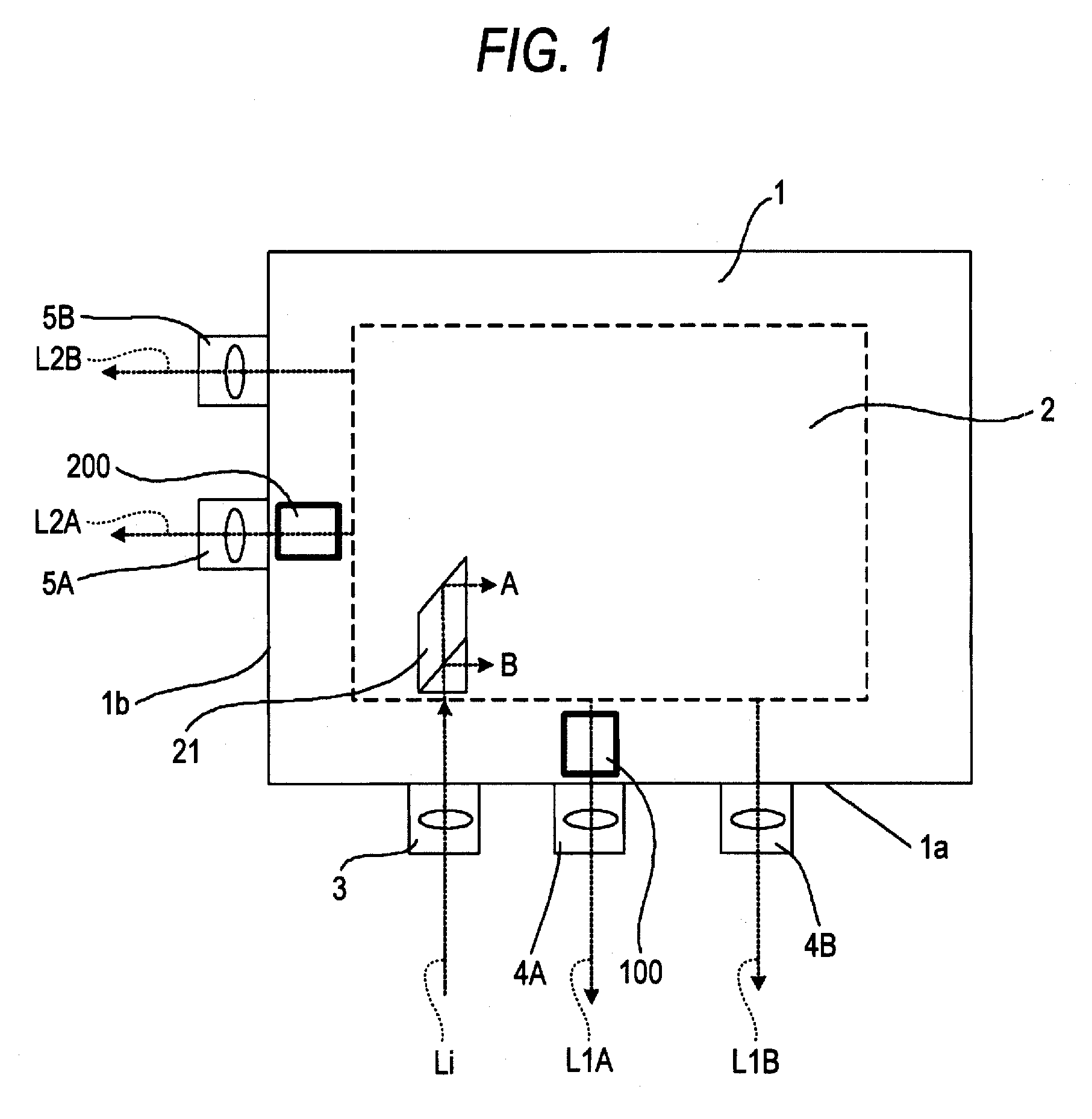
[0023]Hereinafter, the invention will be described in more detail with reference to the drawings. FIG. 1 is a functional block diagram showing an embodiment of a delay interferometer to which the invention is applied. The embodiment is a small delay interferometer having a package configuration in which a Michelson delay interferometer unit is mounted in a package having first and second sidewall portions that are perpendicular to each other, and an output port for one interference output light, and an output port for the other interference output light are perpendicularly distributed in the first and second sidewall portions, respectively.

[0024]Referring to FIG. 1, a Michelson delay interferometer unit 2 is mounted in a quadrilateral package 1 having in the first and second sidewall portions 1a, 1b that are perpendicular to each other. Input light Li is input into the Michelson delay interferometer unit 2 through an input port 3 disposed in the first sidewall portion 1a.

[0025]The ...


PUM


Abstract

In a delay interferometer in which a Michelson delay interferometer unit is mounted in a package, the delay interferometer includes: a Michelson delay interferometer unit in which A-channel interference output light obtained by optically processing input light that is formed by splitting input light received through an input port, into A and B channels through a splitting portion is output from an A-channel first output port and an A-channel second output port disposed, and B-channel interference output light is output from a B-channel first output port and a B-channel second output port; and a first optical path length compensating member which is interposed between the A-channel interference output light or the B-channel interference output light, and the A-channel first output port or the B-channel first output port.

Description

[0001]This application claims priority to Japanese Patent Application No. 2008-152243, filed Jun. 10, 2008, in the Japanese Patent Office. The Japanese Patent Application No. 2008-152243 is incorporated by reference in its entirety.TECHNICAL FIELD[0002]The present disclosure relates to a delay interferometer using a spatial optical system, which is used for demodulating a differential phase shift keying signal in optical fiber communication, particularly in optical fiber communication using a dense wavelength division multiplexing (DWDM) system.RELATED ART[0003]In optical fiber communication using a DWDM system, an optical signal which is modulated by the differential phase shift keying method (DPSK) or the differential quadrature phase shift keying method (DQPSK) is mainly transmitted, and a received optical signal is demodulated by a demodulator including a delay interferometer.[0004]As a delay interferometer using a spatial optical system, a Michelson delay interferometer is well...

Claims


Application Information

Patent Timeline
IPC IPC(8): G01B9/02G01J3/45G02F2/00
CPCG02B6/2861H04B10/677G02B6/29349
Inventor ASANO, JUNICHIROIEMURA, KOKIHIHARA, MAMORU
Owner YOKOGAWA ELECTRIC CORP
Why Eureka
Try Eureka