CDM signal transmitter with modulators reduced in number and a method therefor

Inactive Publication Date: 2010-01-07
OKI ELECTRIC IND CO LTD
View PDF4 Cites 2 Cited by
  • Summary
  • Abstract
  • Description
  • Claims
  • Application Information

AI Technical Summary

Benefits of technology

[0007]It is an object of the present invention to provide a CDM signal transmitter and a code division multiplexing method that allow required modulators to be reduced to curb the rising cost of parts and components and prevent the circuit size from increasing.
[0008]The inventor has made a keen study and found that modulators required can be reduced in number by adding up transmission data on a plurality of channels to produce resultant added data and modulating pieces of bit transmission data which are indicative of the values of the respective bits of the added data, when expressed in binary form, the pieces of bit transmission data being equal in number to the bit positions of the added data expressed in binary form.
[0014]In this way, pieces of transmission data corresponding in number to N channels are added to produce-added data and then produce pieces of bit transmission data which are indicative of the values of the respective bits of the added data, when expressed in binary form, and are equal in number to M bit positions of the added data in the binary form, and the obtained bit transmission data are multiplexed. Consequently, the number of modulators required is equal to the number (M) of the bit positions. The modulators can therefore t be reduced compared to the conventional technique.
[0016]In addition, if the CDM signal transmitter further includes the offset adjuster and the operational circuit also has the offset calculator, a DC offset possibly occurring in a CDM signal depending on the number of channels N can easily be corrected.

Problems solved by technology

Thus, the number of modulators increases with an increase in number of channels, resulting in an increase in cost for required parts and components.
Moreover, the circuit size of the multiplexer increases, so that the manufacture of multiplexer becomes difficult.

Method used


Image

  • CDM signal transmitter with modulators reduced in number and a method therefor
  • CDM signal transmitter with modulators reduced in number and a method therefor
  • CDM signal transmitter with modulators reduced in number and a method therefor

Examples


Embodiment Construction

[0021]In the following, a preferred embodiment of the present invention will be described in detail with reference to the accompanying drawings which are simplified as far as the present invention can be understood. It is to be noted that the following preferred embodiment is only illustrative and is not to be intended to limit in any respect, and thus various changes and modifications may be made within the scope of the present invention.

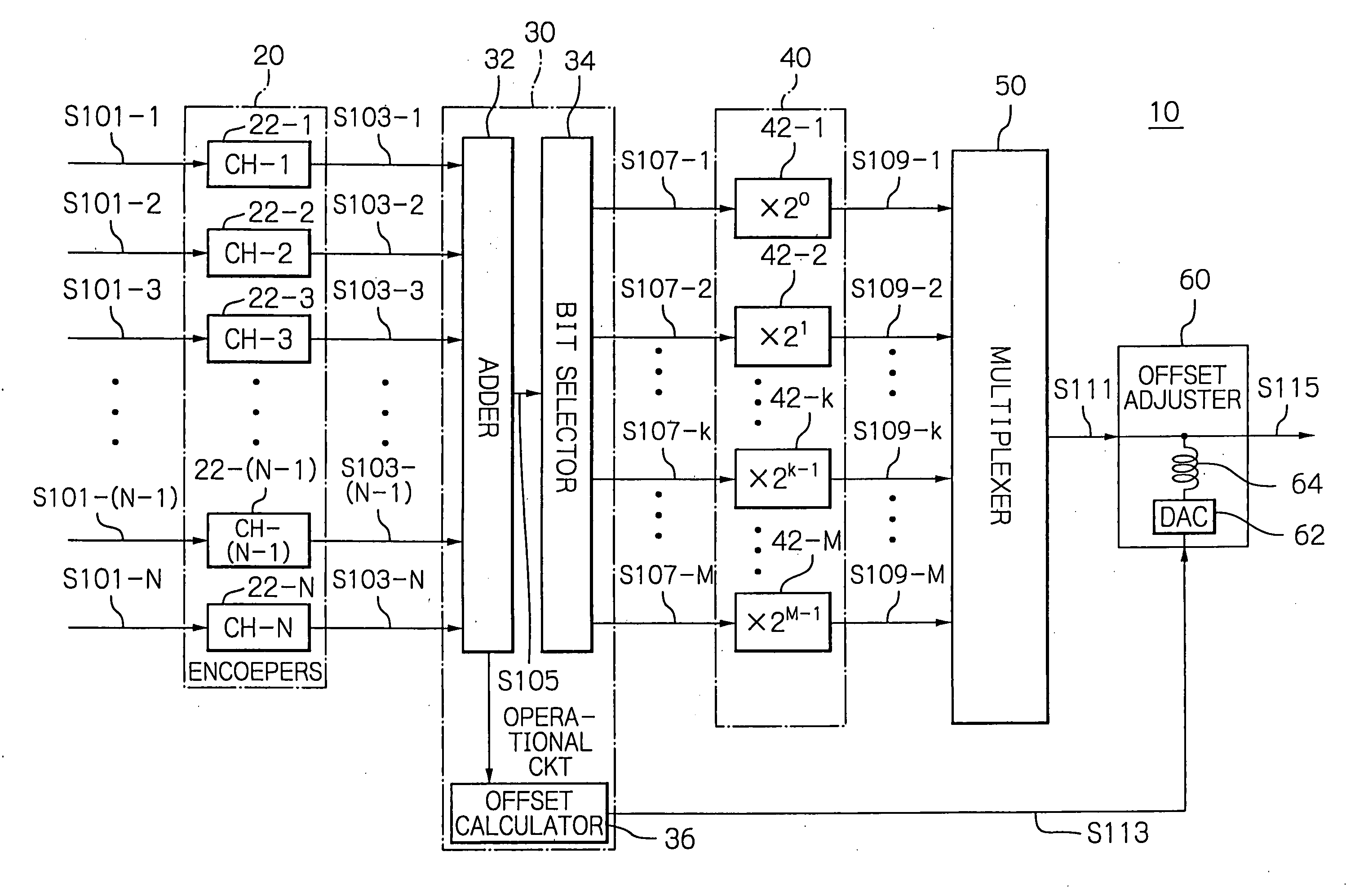
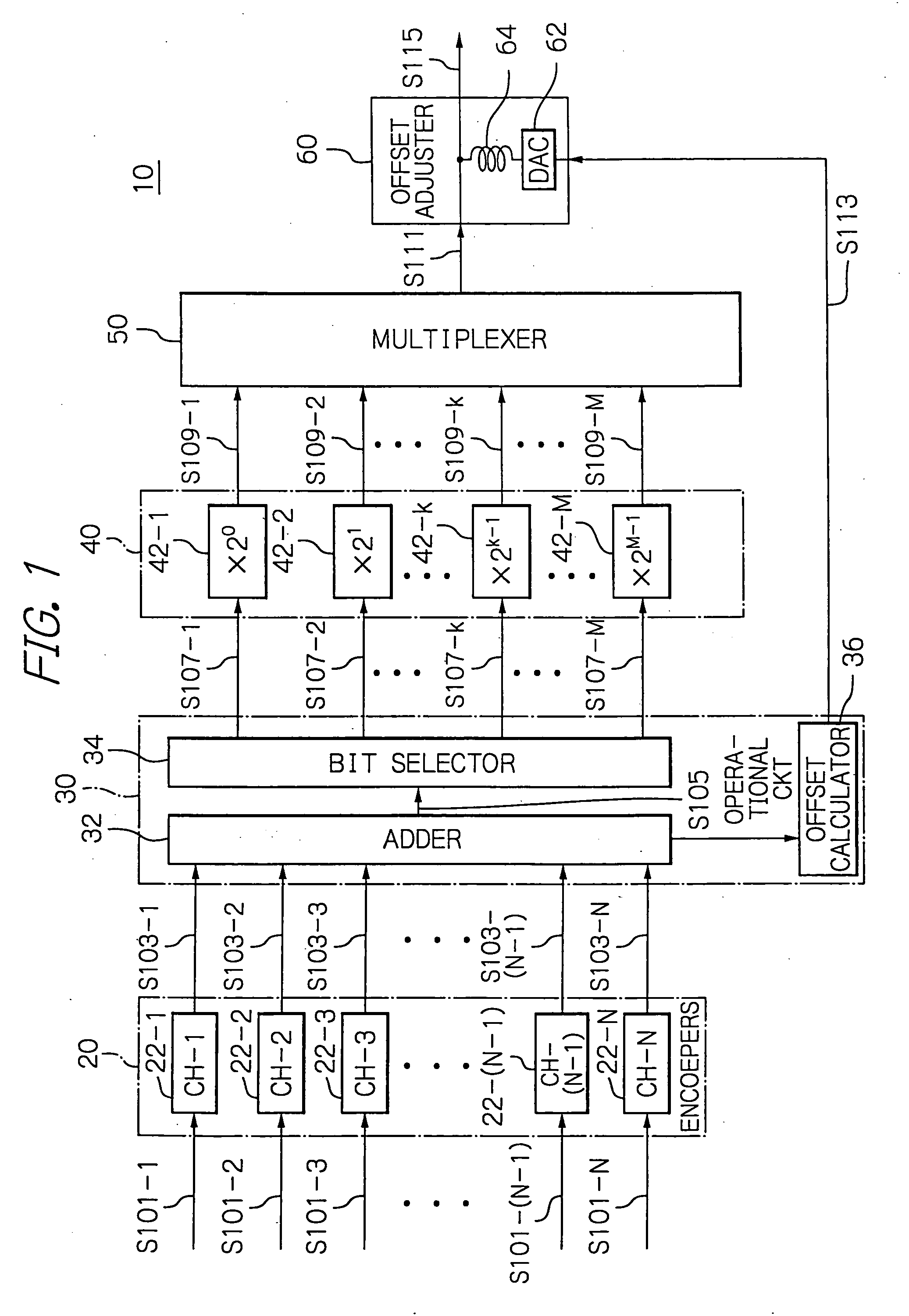
[0022]FIG. 1 is a schematic block diagram showing a code division multiplex (CDM) signal transmitter 10 in accordance with an illustrative embodiment of the present invention. The CDM signal transmitter 10 is fed with transmission data on a plurality (N) of-channels depicted with arrows S101-1 to S101-N in the figure, where N is an integer larger than unity, to produce a CDM signal S115 from the transmission data S101-1 to S101-N.

[0023]The CDM signal transmitter 10 comprises an encoder unit 20, an operational circuit 30, a modulator unit 40, a mult...


PUM


Abstract

A code division multiplex signal transmitter includes an operational circuit, a modulator unit and a multiplexer. The operational circuit adds up input transmission data on channels to produce resultant added data and modulates pieces of bit transmission data which are indicative of the values of the respective bits of the added data, when expressed in binary form, the pieces of bit transmission data being equal in number to the M bit positions of the added data expressed in binary form. The modulator unit includes modulators corresponding in number to the M bit positions of the added data in the binary form. A k-th modulator, where k is an integer of 1 to M, inclusive, modulates a k-th piece of bit transmission data to produce a k-th bit modulated signal whose amplitude level is 2k-1. The multiplexer multiplexes first to M-th bit modulated signals to produce a code division multiplex signal.

Description

BACKGROUND OF THE INVENTION[0001]1. Field of the Invention[0002]The present invention relates to a code division multiplex signal transmitter, and more particularly to a code division multiplex signal transmitter for use on a transmitting end in a code division multiplex communication system. The present invention also relates to a code division multiplexing method therefor.[0003]2. Description of the Background Art[0004]A telecommunications network system relying upon the code division multiplexing (CDM) allows several pieces of transmission data to be multiplexed into one time slot. The CDM technique may, when applied to a telecommunications system, advantageously transmit large volumes of data with communications resources such as time slot saved, thus being put to practical use mainly in mobile communications.[0005]Now, with a conventional CDM signal transmitter disclosed by, for example, U.S. Pat. No. 7,342,909 to Matsuno et al., a CDM signal transmitter is supplied with transm...

Claims


Application Information

Patent Timeline
IPC IPC(8): H04L27/00H04J13/00H04B1/04H04B1/707
CPCH04B1/707H04J13/0003H04B2201/70707
Inventor TAMAI, HIDEAKI
Owner OKI ELECTRIC IND CO LTD
Why Eureka
Try Eureka