Determining drillstring neutral point based on hydraulic factor

Inactive Publication Date: 2009-06-25
SCHLUMBERGER TECH CORP
View PDF12 Cites 2 Cited by
  • Summary
  • Abstract
  • Description
  • Claims
  • Application Information

AI Technical Summary

Benefits of technology

[0007]A fourth aspect of the invention is directed to a method of providing a system for determining a neutral point of a drillstring in drilling a borehole, the method comprising: at least one of creating, maintaining, deploying and supporting a computer infrastructure operable to: receive depth-time log data

Problems solved by technology

However, the estimation / simulation may deviate from the situations in the actual drilling.

Method used


Image

  • Determining drillstring neutral point based on hydraulic factor
  • Determining drillstring neutral point based on hydraulic factor
  • Determining drillstring neutral point based on hydraulic factor

Examples


Embodiment Construction

[0015]Advantages and features of the present invention may be understood more readily by reference to the following detailed description of exemplary embodiments and the accompanying drawings. The present invention may, however, be embodied in many different forms and should not be construed as being limited to the embodiments set forth herein. Rather, these embodiments are provided so that this disclosure will be thorough and complete and will fully convey the concept of the invention to those skilled in the art, and the present invention will only be defined by the appended claims. Like reference numerals refer to like elements throughout the specification.

1. SYSTEM OVERVIEW

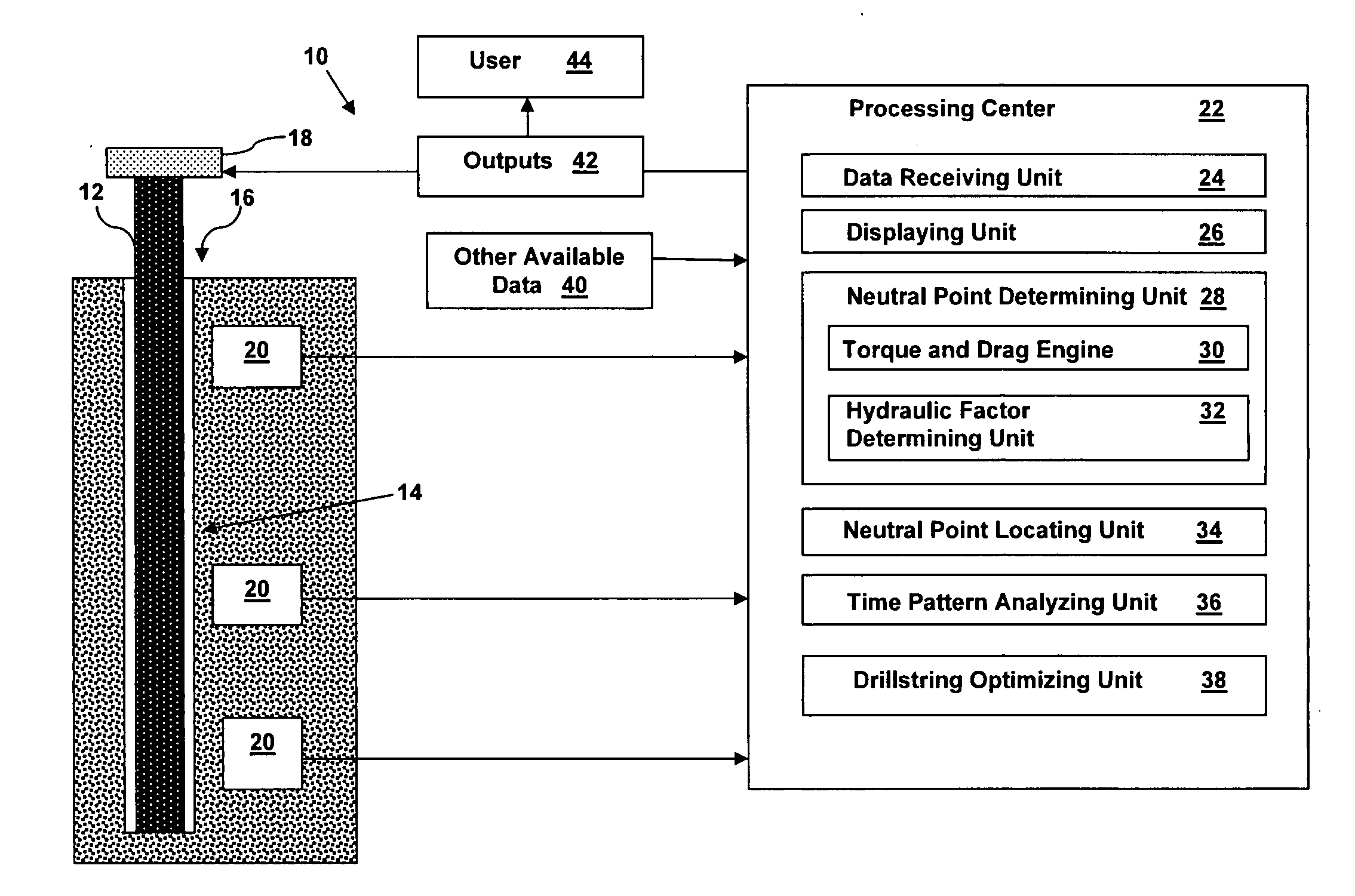
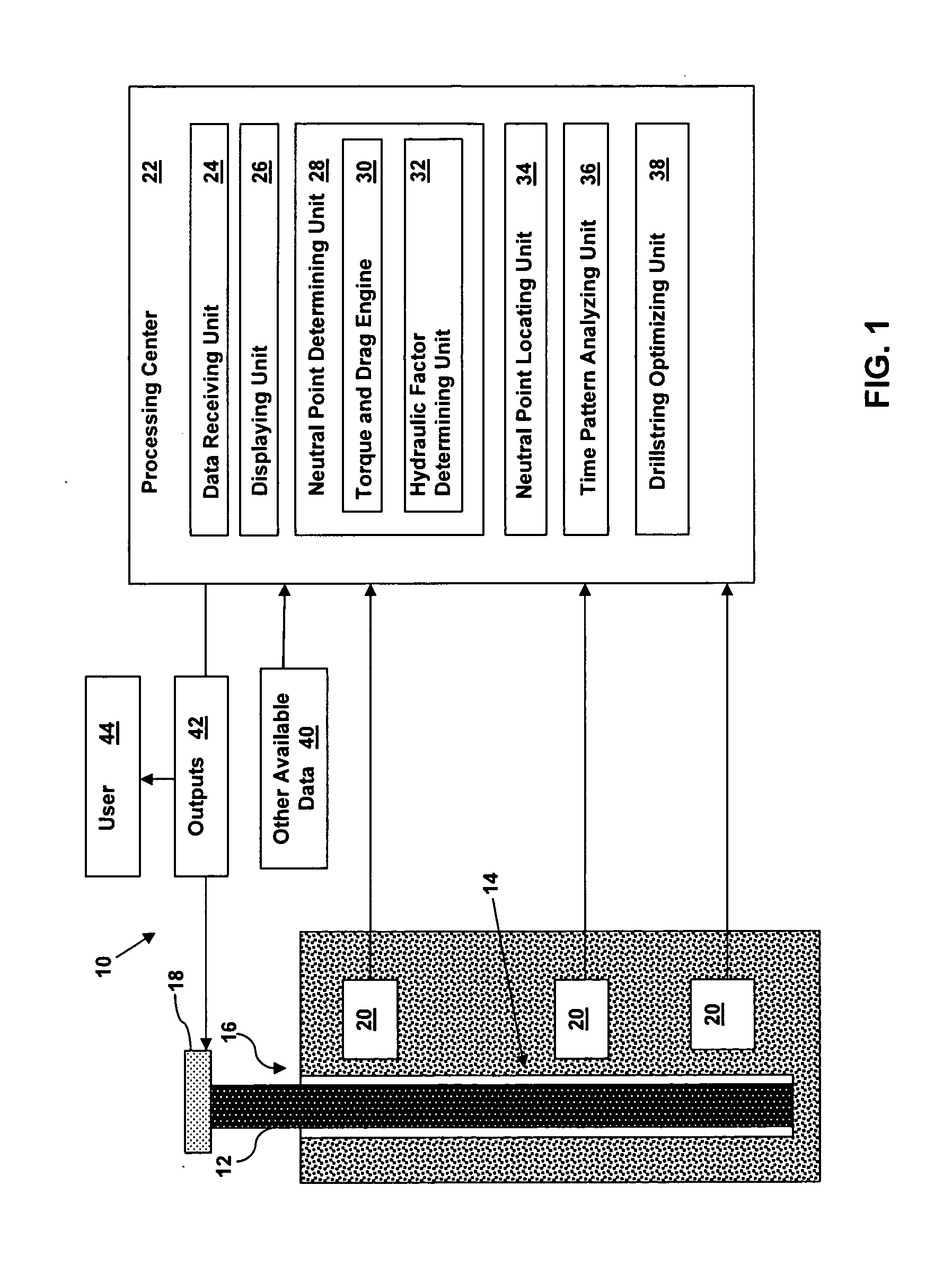
[0016]Referring to FIG. 1, a schematic diagram of an illustrative system 10 for determining a neutral point of a drillstring 12 in drilling a borehole 14 in a reservoir 16 is shown. In FIG. 1, borehole 14 is shown as a vertical well, but may also be other type of wells, such as a deviated well including a horiz...


PUM


Abstract

A solution for determining a neutral point of a drillstring in drilling a borehole is disclosed. A method may comprise: receiving depth-time log data for drilling the borehole with the drillstring, the depth-time log data including data related to a torque and drag factor and data related to a hydraulic factor; and determining the neutral point of the drillstring at a time point during the drilling based on the torque and drag factor and the hydraulic factor.

Description

FIELD OF THE INVENTION[0001]The disclosure relates in general to reservoir development, and more particularly to determining a neutral point of a drillstring in drilling a borehole based on hydraulic and / or torque and drag factors.BACKGROUND OF THE INVENTION[0002]In oil reservoir development, a drillstring is used to drill a borehole (well). The term “drillstring” refers to the combination of the drillpipe, the bottomhole assembly and any other tools used to make the drill bit turn at the bottom of the wellbore. During the drilling, the neutral point of the drillsring needs to be considered for various reasons, such as stress reduction and management. A neutral point is the point at which the drillstring moves from a state of compression stress to a state of tension stress. Components of the drillstring below the neutral point are in compression stress such that they need to have high bending stiffness to avoid, for example, buckling. In addition, if there is a jarring device in the...

Claims


Application Information

Patent Timeline
IPC IPC(8): G01V3/38E21B47/00
CPCE21B44/00
Inventor GUIDRY, JONATHANSHI, XIAOYANMEEHAN, RICHARDFANG, JOSEPHLAN, LI
Owner SCHLUMBERGER TECH CORP
Why Eureka
Try Eureka