Gas sensor and method of making

a technology of gas sensor and gas sensor, which is applied in the direction of electrochemical variables of materials, instruments, coatings, etc., can solve the problems of reducing the performance of catalysts upon exposure to sosub>x /sub>and water vapor, and reducing the efficiency of emissions control schemes that adversely affect or limit efficiency. commercially viable, and reducing the effect of emissions

Inactive Publication Date: 2009-06-25
AMPHENOL THERMOMETRICS
View PDF5 Cites 36 Cited by
  • Summary
  • Abstract
  • Description
  • Claims
  • Application Information

AI Technical Summary

Problems solved by technology

Development of cost-effective gas sensors that can give reliable readout at such low concentration levels of analyte, and which can deliver robust performance even in harsh environments, is one of the major challenges facing present day emissions monitoring technology.
While the lean burn technology improves the efficiency of the engine, it also results in higher NOx emissions.
Any emissions control scheme that adversely impacts or limits efficiency will not be commercially viable.
However, the performance of the catalyst degrades upon exposure to SOx and water vapor, as are commonly present in the exhaust from automobiles.
This is one of the factors contributing to lowering the working life of such gas sensors.
Further, the relatively intricate design of these gas sensors makes them expensive to replace on a regular basis.
As with any technology, this technology presents situation specific disadvantages and advantages.
These gas sensors however, are sensitive to a broad range of gases, and therefore are of limited utility in such applications.
Furthermore, these gas sensors are prone to long term instability because of their polycrystalline nature.

Method used

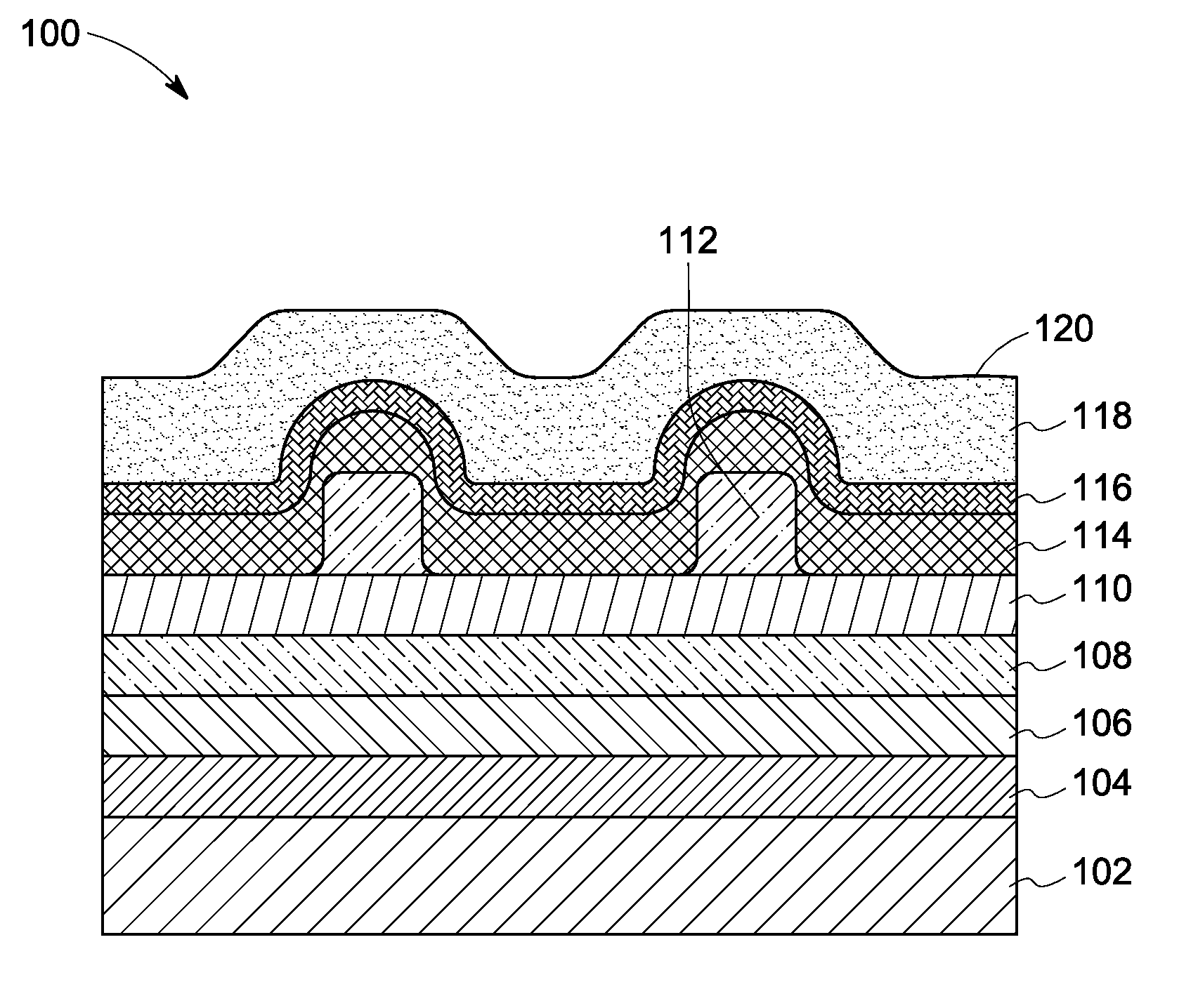
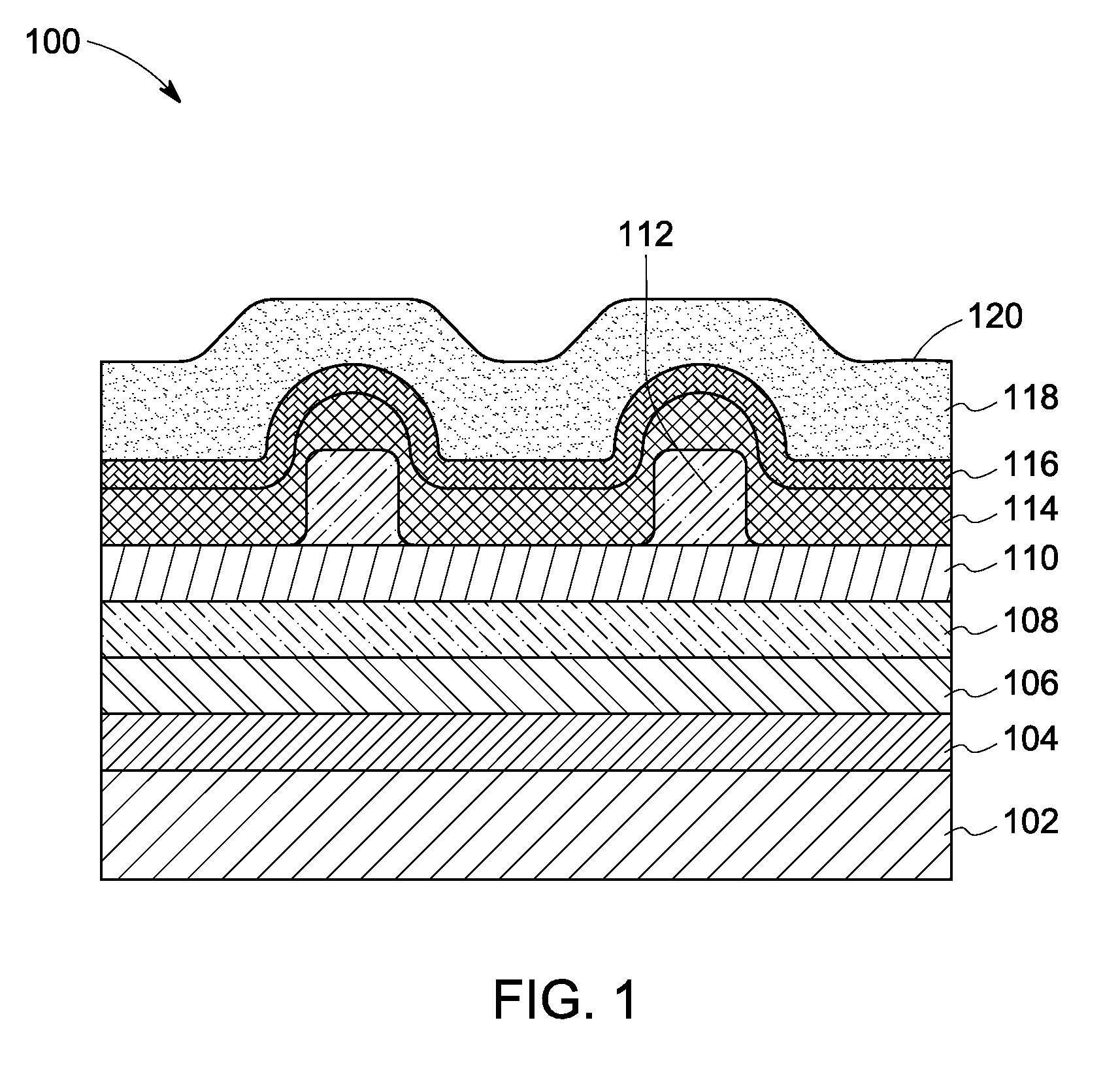
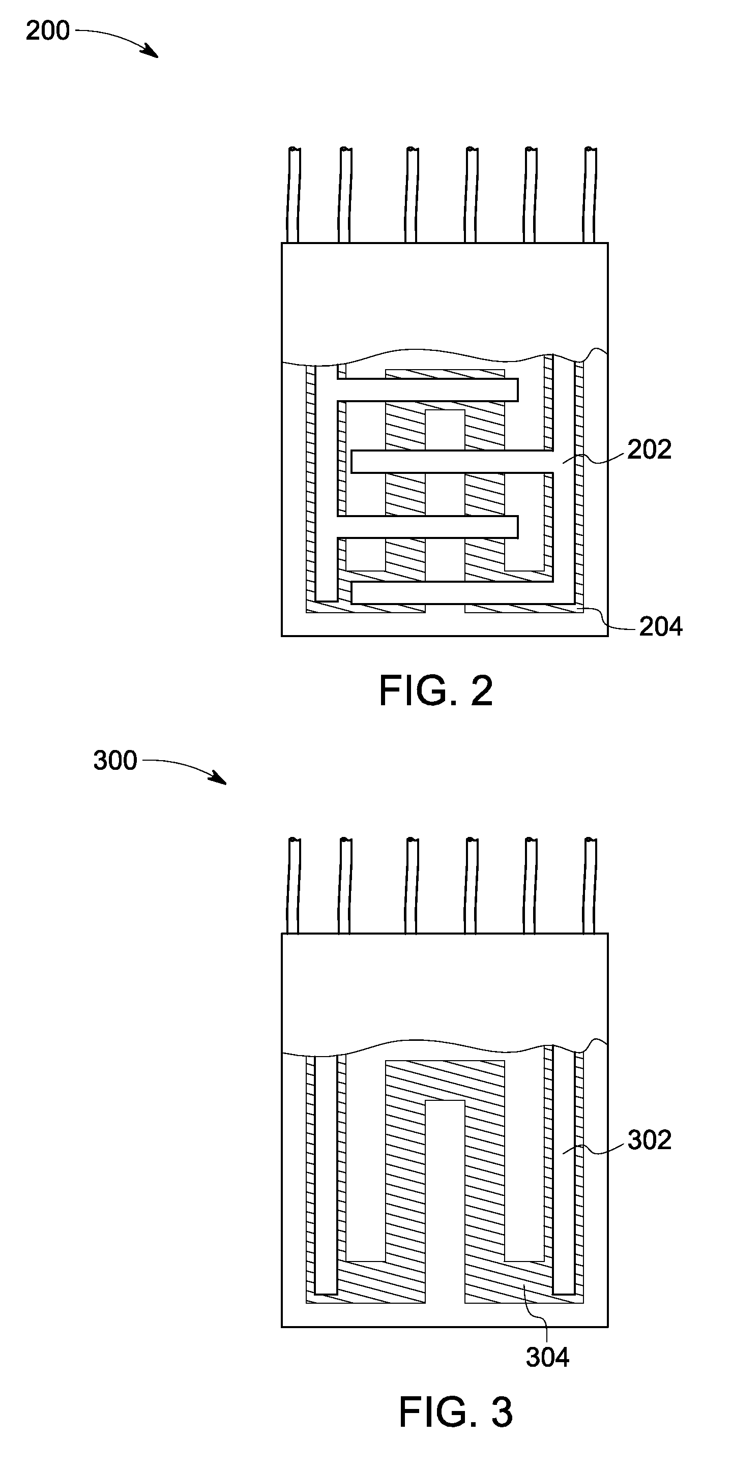

Image

  • Gas sensor and method of making
  • Gas sensor and method of making
  • Gas sensor and method of making

Examples


Embodiment Construction

[0021]In the following description, whenever a particular aspect or feature of an embodiment of the invention is said to comprise or consist of at least one element of a group and combinations thereof, it is understood that the aspect or feature may comprise or consist of any of the elements of the group, either individually or in combination with any of the other elements of that group.

[0022]A gas sensor may be used to determine if an “analyte” is present and / or to quantify an amount of the analyte. As used herein, the term “analyte” may refer to any substance to be detected and / or quantified, including but not limited to a gas, a vapor, a bioanalyte, particulate matter, and a combination thereof.

[0023]Since the primary constituents of NOx, i.e., NO and NO2 are interconvertible, reliable estimation of total NOx may be achieved if the response of the gas sensor, i.e., the NOx concentration dependent change in resistance of the gas sensor is equal (in terms of magnitude and sign) for...


PUM

PropertyMeasurementUnit
response timeaaaaaaaaaa
recovery timeaaaaaaaaaa

Abstract

A gas sensor is disclosed. The gas sensor includes a gas sensing layer including at least one chemical compound with the general chemical formula MαO62Nγ, wherein M is at least one chemical element selected from the group consisting of W, Ti, Ta, Sr, Mo, and combinations thereof, and α, β, γ are self-consistent, said gas sensing layer being capable of detecting at least one gas selected from the group consisting of NO, NO2, SO2, O2, H2O, CO, H2, and NH3, at least one electrode positioned within a adhesion layer composed of a material selected from the group consisting of Ti, Cr, and combinations thereof, and a response modification layer composed of a material selected from the group consisting of Mg, Ti, V, Cr, Mn, Co, Ni, Zn, Nb, Ru, Rh, Pd, Ta, W, Re, Pt, and combinations thereof. The at least one electrode is in communication with the sensing layer. A method of fabricating the gas sensor is also disclosed.

Description

BACKGROUND[0001]The invention relates generally to the area of gas sensing. More specifically, the invention relates to the sensing of NOx gas.[0002]Environmental considerations are the primary motivating factors to develop NOx gas sensors. NOx emissions react with gases such as SOx, CO and moisture (water vapor) in the air to produce smog and acid rain. One of the major sources of NOx emissions is internal combustion engine exhaust.[0003]The European Euro VI emission standards for light commercial vehicles (category N1-I, N1-II and N1-III), to be implemented by September 2015, require NOx emission levels below 0.5 gm / hp-hr. This typically translates to less than 50 ppm of NOx tail pipe emissions. Development of cost-effective gas sensors that can give reliable readout at such low concentration levels of analyte, and which can deliver robust performance even in harsh environments, is one of the major challenges facing present day emissions monitoring technology.[0004]The current par...

Claims


Application Information

Patent Timeline
Patent Type & Authority Applications(United States)
IPC IPC(8): G01N27/26B05D5/12
CPCG01N27/125
Inventor CUI, JUNLEMMON, JOHN PATRICKKRISHNA, KALAGA MURALIKARAVOOR, GEETHA
Owner AMPHENOL THERMOMETRICS
Why Eureka
Try Eureka