Fuel injection valve for internal combustion engine

a technology for internal combustion engines and fuel injection valves, which is applied in the direction of functional valve types, machines/engines, mechanical apparatus, etc., can solve the problems of difficulty in maintaining fuel injection performance, no water repellent performance no hydrophilic property of pas thermally decomposed, etc., to achieve high hydrophilic property, maintain fuel injection performance, and high hydrophilic property

Active Publication Date: 2009-06-25
DENSO CORP
View PDF8 Cites 29 Cited by
  • Summary
  • Abstract
  • Description
  • Claims
  • Application Information

AI Technical Summary

Benefits of technology

[0011]With this structure of the injection valve, when the nozzle hole is opened, fuel is injected through the nozzle hole. In this case, a portion of the injected fuel remains on the covering layer disposed on the outer surface of the valve guide. Because the covering layer has a hydrophilic property higher than that of the surface of the valve guide, the covering layer prevents the fuel remaining on the layer from being solidified or caked as deposits on the layer around the outlet opening of the nozzle hole.
[0012]More specifically, the covering layer having a high hydrophilic property successively collects water contained in the fuel and forms a film of the water on the layer. When a portion of fuel injected from the hole remains on the covering layer as residues containing non-burned carbons, P, Zn, Si, compounds of carboxylic acids and base components, and the like, the fuel residues float on the water film. In this case, the injection flow of the fuel easily removes the fuel residues from the water film su

Problems solved by technology

In this case, it is difficult to maintain the fuel injection performance of the injection valve at a superior level.
However, this injection valve in the Publication No. 2001-90638 has the problem that FAS thermally decomposed is a

Method used


Image

  • Fuel injection valve for internal combustion engine
  • Fuel injection valve for internal combustion engine
  • Fuel injection valve for internal combustion engine

Examples


embodiment 1

Modification of Embodiment 1

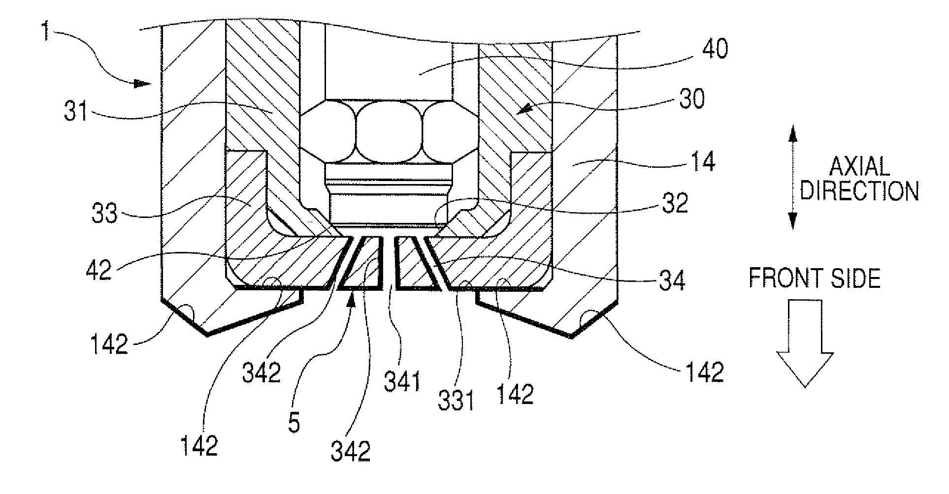
[0049]FIG. 4 is an enlarged view of the covering layer 5 attached to surfaces of the nozzle body 30 according to a modification of the first embodiment. In the injector 1 according to the first embodiment, the covering layer 5 having a high hydrophilic property is attached to only the surface 331 of the nozzle hole plate 33 of the nozzle body 30 around the outlet openings 341 of the respective holes 34. However, as shown in FIG. 4, because fuel injected from the holes 34 passes across inner circumferential surfaces 342 of the holes 34, the covering layer 5 may be attached to the inner circumferential surfaces 332 of the holes 34 as well as the surface 331 of the plate 33. Further, because fuel sprayed from the holes 34 comes in contact with surfaces 142 of the front end portion 141 of the nozzle holder 14, the covering layer 5 may be attached to the surfaces 142 of the nozzle holder 14.

[0050]Accordingly, the injector 1 can prevent deposits of fuel from be...

embodiment 2

[0052]In the first embodiment, the nozzle body 30 has the nozzle body wall 31 and the nozzle hole plate 33 which are separately formed and are attached to each other as one unit in the injector 1. However, the nozzle body wall 31 and the nozzle hole plate 33 may be integrally formed.

[0053]FIG. 5 is an enlarged view of the covering layer 5 attached to surfaces of a nozzle body according to the second embodiment.

[0054]As shown in FIG. 5, the nozzle body 30 has a wall portion fixed to the inner circumferential surface of the holder 14 and a conical portion 301 extending from the front end of the wall portion. These portions are integrally formed with each other. The valve seat 32 is disposed on the inner circumferential surface of the conical portion 301. The nozzle holes 34 are disposed at the front end of the conical portion 301 of the body 30. The conical portion 301 of the body 30 is protruded from the holder 14.

[0055]The covering layer 5 is attached to an outer circumferential sur...


PUM


Abstract

A fuel injection valve has a valve guide, a valve member movable in a center opening of the valve guide along an axial direction of the valve guide, and a covering layer disposed on a surface of the valve guide. The valve guide has a valve seat placed on an inner surface thereof and a nozzle hole from which fuel is injected. The valve member is seated on the valve seat to close the nozzle hole and leaves the valve seat to open the nozzle hole. The covering layer is placed around an outlet opening of the nozzle hole. The covering layer is made of boron nitride in a hexagonal crystal system so as to have a hydrophilic property higher than that of the surface of the valve guide.

Description

CROSS-REFERENCE TO RELATED APPLICATION[0001]This application is based upon and claims the benefit of priority of the prior Japanese Patent Application 2007-332574 filed on Dec. 25, 2007, so that the contents of which are incorporated herein by reference.BACKGROUND OF THE INVENTION[0002]1. Field of the Invention[0003]The present invention relates to a fuel injection valve which injects fuel into a combustion chamber of an internal combustion engine or the like.[0004]2. Description of Related Art[0005]An internal combustion engine has a fuel injection valve for injecting fuel into each of a plurality of combustion chambers. This injection valve has a valve guide formed in a cylindrical shape and a valve member. The valve guide has nozzle holes. The valve member is disposed in a center opening of the guide. The valve member is reciprocated to be seated on a valve seat of the guide and to leave the seat. Therefore, the holes are repeatedly opened and closed. A fuel passage is formed bet...

Claims


Application Information

Patent Timeline
IPC IPC(8): F02M61/10B05B1/32
CPCF02M51/0671F02M2200/9038F02M2200/06F02M61/1813
Inventor SUZUKI, KAZUNORIOOZONO, ATSUSHI
Owner DENSO CORP
Why Eureka
Try Eureka