Mechanical valve

a mechanical valve and valve body technology, applied in the field of mechanical valves, can solve the problems of increased cost and complication of assembly operation, increased cost, and increased cost, and achieve the effect of simple structur

Inactive Publication Date: 2009-06-25
TEAC CORP +1
View PDF13 Cites 20 Cited by
  • Summary
  • Abstract
  • Description
  • Claims
  • Application Information

AI Technical Summary

Benefits of technology

[0012]According to the present invention, switchable air supply becomes possible by driving one shaft by utilization of magnetic force. Therefore, a compact mechanical valve having a simple structure is acquired.

Problems solved by technology

However, the air pressure switching mechanism described in JP 9-144911 A has a large number of components and encounters various problems, such as an increase in cost and complication of assembling operation.
Therefore, there has been a problem of a mechanism for actuating the valve element being likely to become bulky.
Moreover, an expensive motor must be prepared to realize high-speed actuation, which results in a problem of an increase in cost.
In a word, a compact valve having a simple structure has never been available.

Method used


Image

  • Mechanical valve
  • Mechanical valve
  • Mechanical valve

Examples


Embodiment Construction

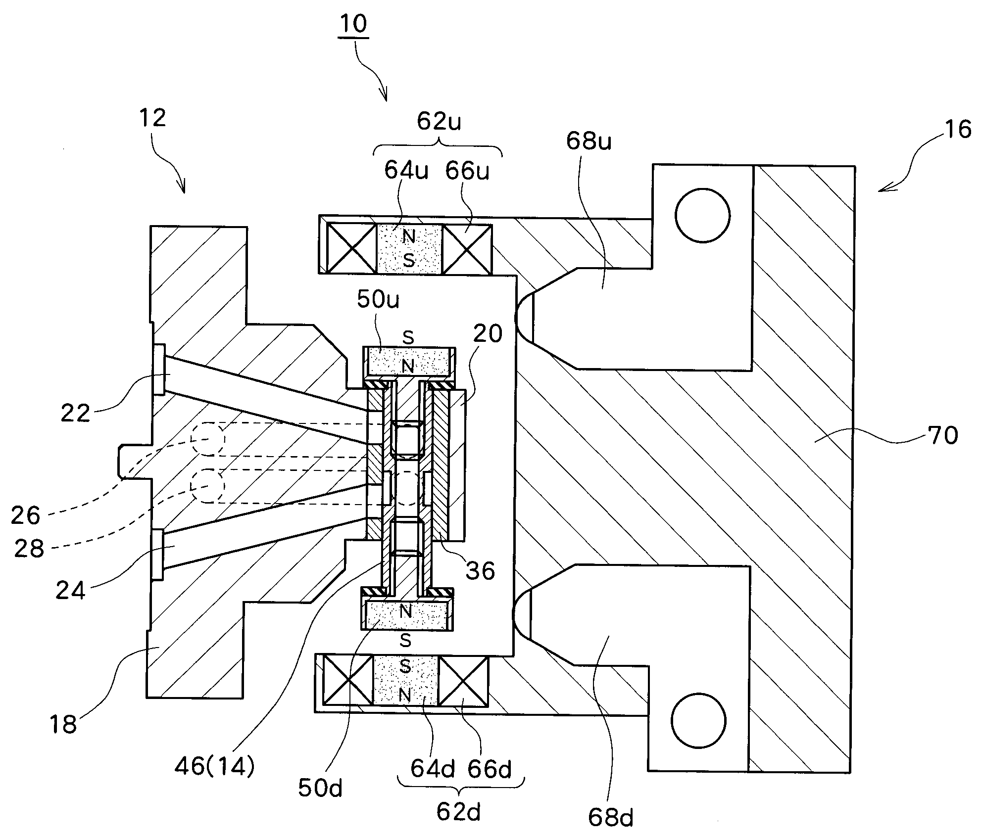
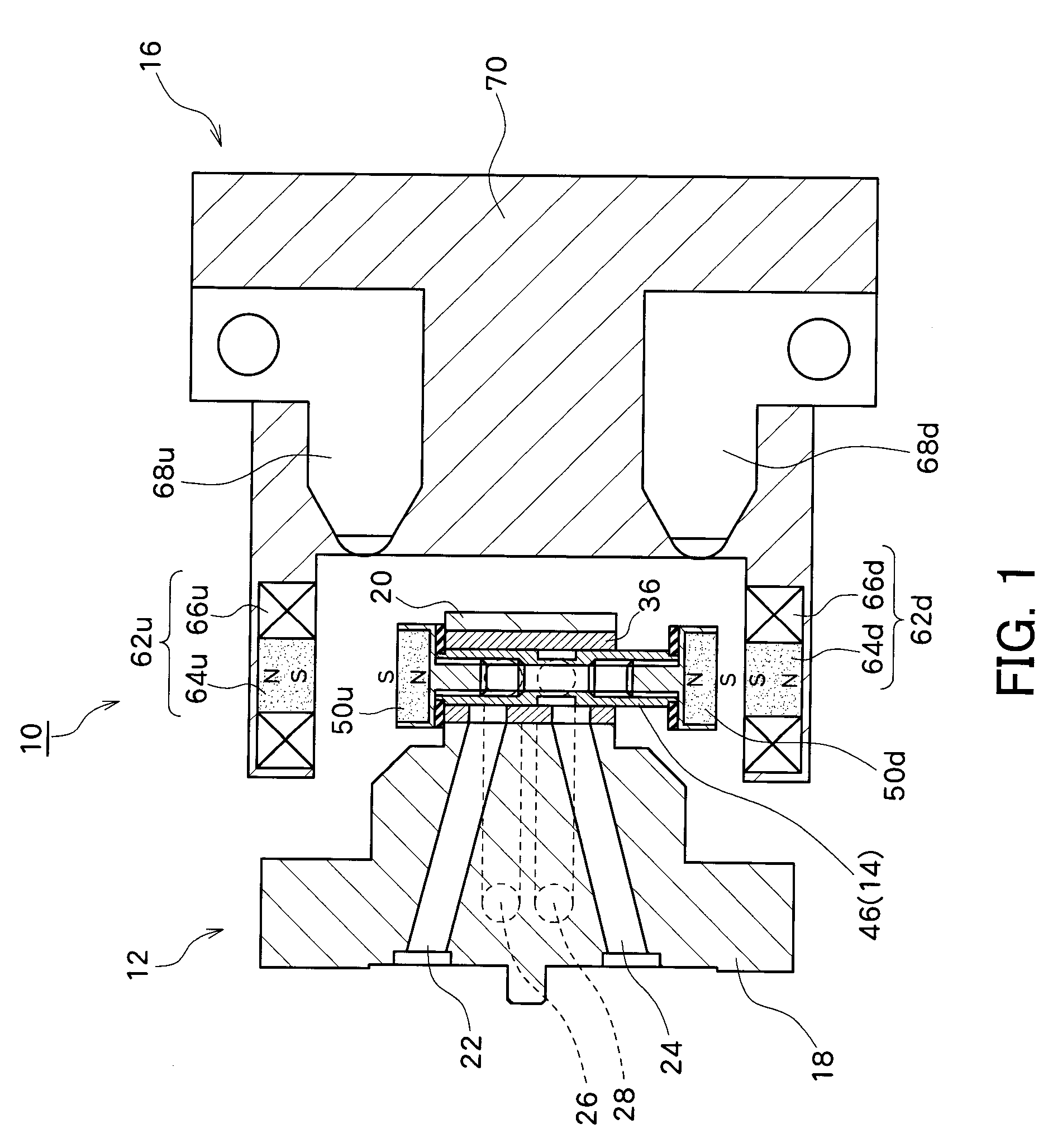
[0026]An embodiment of the present invention will be described hereunder by reference to the drawings. FIG. 1 is a cross-sectional view of a mechanical valve 10 of an embodiment of the present invention. The mechanical valve 10 is a valve assumed to be used in an electronic component automatic placement apparatus (not shown) that places electronic components on a circuit board. Specifically, the electronic component automatic placement apparatus is equipped with a head that can move in directions X, Y, and Z, and the head is equipped with a suction nozzle that holds an electronic component by suction. The mechanical valve 10 of the present embodiment is a valve for supplying switchably the suction nozzle with positive-pressure air or negative-pressure air.

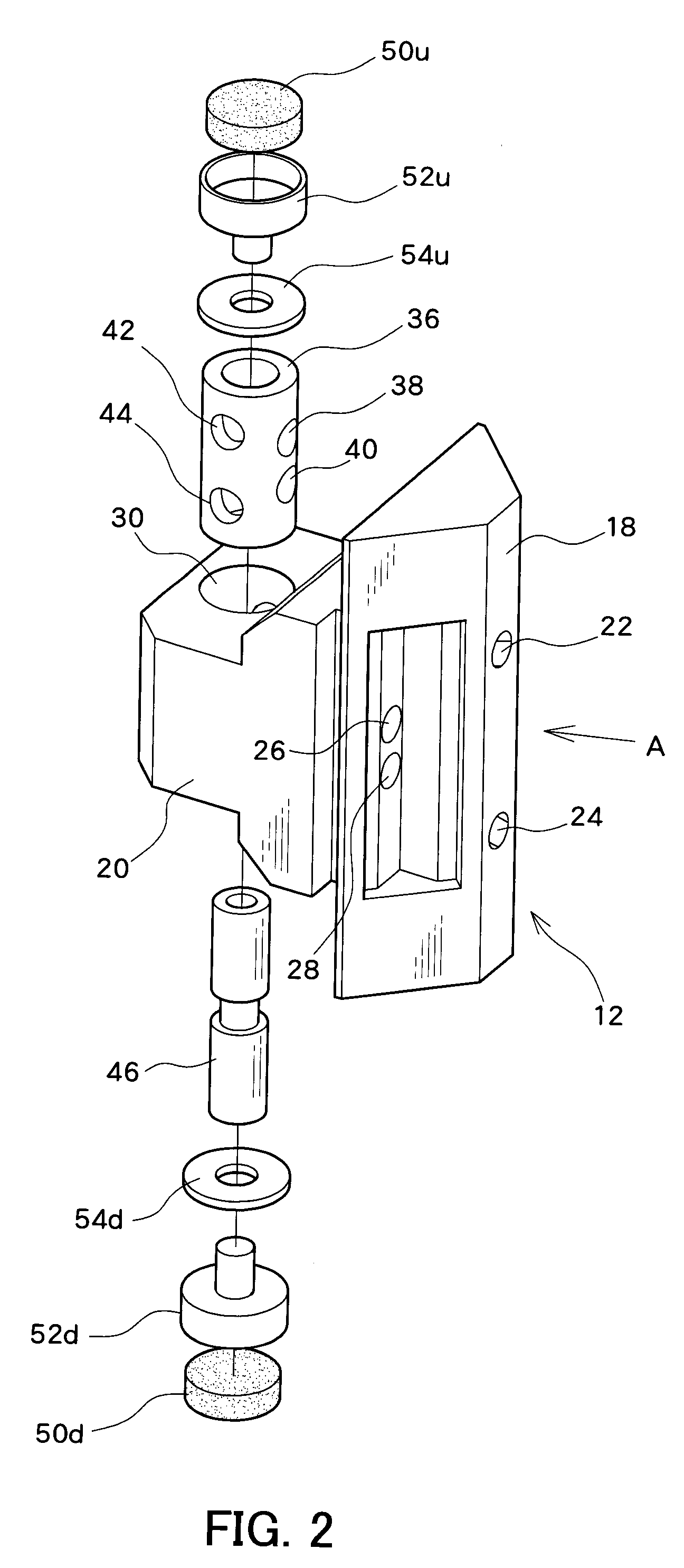
[0027]The mechanical valve 10 is broadly divided into a main body 12 attached to a head of the electronic component automatic placement apparatus; a movable element 14 that moves forwardly and rearwardly with respect to the main bo...


PUM


Abstract

A mechanical valve has a main body having a cylinder hole formed therein, a movable element that is inserted into the cylinder hole and that moves forwardly and rearwardly, and a drive section that drives the movable element. A plurality of openings through which air passes are formed in an internal peripheral surface of the cylinder hole, and the openings are opened and closed as a result of forward and rearward movements of the movable element. A movable magnet is fastened to each of both ends of the movable element. Electromagnets opposing the respective movable magnets are provided in a drive section. The movable element is actuated by utilization of magnetic force of the electromagnets.

Description

PRIORITY INFORMATION[0001]This application claims priority to Japanese Patent Application No. 2007-320904 filed on Dec. 12, 2007 which is incorporated herein by reference in its entirety.BACKGROUND[0002]1. Technical Field[0003]The present invention relates to a mechanical valve capable of switching between a first state in which the passage of first air is permitted and a second state where the passage of second air is permitted.[0004]2. Related Art[0005]A compact valve capable of being actuated at high speed has recently been sought. For instance, such a valve is used in an electronic component automatic placement machine that places electronic components on a printed circuit board. The electronic component automatic placement machine has a suction nozzle that holds an electronic component by suction. The suction nozzle is switchably supplied with negative-pressure air and positive-pressure air, thereby sucking a component and releasing the thus-sucked component. With a view toward...

Claims


Application Information

Patent Timeline
Patent Type & Authority Applications(United States)
IPC IPC(8): F16K31/02
CPCF16K31/082F16K11/07
Inventor MATSUNAGA, HIROSHISAITO, ATSUSHI
Owner TEAC CORP
Why Eureka
Try Eureka