Low risk deployment driver airbag system

a driver airbag and low-risk technology, applied in the direction of pedestrian/occupant safety arrangement, vehicle components, vehicular safety arrangements, etc., can solve the problems of increased development cost for car makers, increased test requirements, and complicated airbag deployment algorithms, so as to save vehicle costs, reduce the output of conventional inflators, and reduce the effect of inflator outpu

Inactive Publication Date: 2009-06-25
CIS TECH LLC
View PDF34 Cites 4 Cited by
  • Summary
  • Abstract
  • Description
  • Claims
  • Application Information

AI Technical Summary

Benefits of technology

[0014]The output of conventional inflators may be reduced significantly due to the benefits of embodiments of the present invention. It is estimated, for example, that the inflator output can be reduced by 30% or more if the secondary upper chamber has 30% of the total volume because the inflator needs to initially inflate only the lower chamber having 70% of the total volume. In other words, the conventional dual stage inflator may be replaced by a single stage inflator that has about 70% of the high output level, which is typically the low output level of the dual stage inflator. The use of low output single stage inflators along with the present invention can not only save cost for the vehicles but also can improve the performance of occupant protection by inflating the airbag at its full pressure equivalent to the high pressure level generated by the high output of the dual stage inflator no matter how severe the crash is and no matter what size of occupant is involved.

Problems solved by technology

However, the cost of the dual stage inflator is much higher than single stage inflators.
It also has increased the development cost to car makers by requiring an increased number of tests and more complicated airbag deployment algorithms.

Method used


Image

  • Low risk deployment driver airbag system
  • Low risk deployment driver airbag system
  • Low risk deployment driver airbag system

Examples


first embodiment

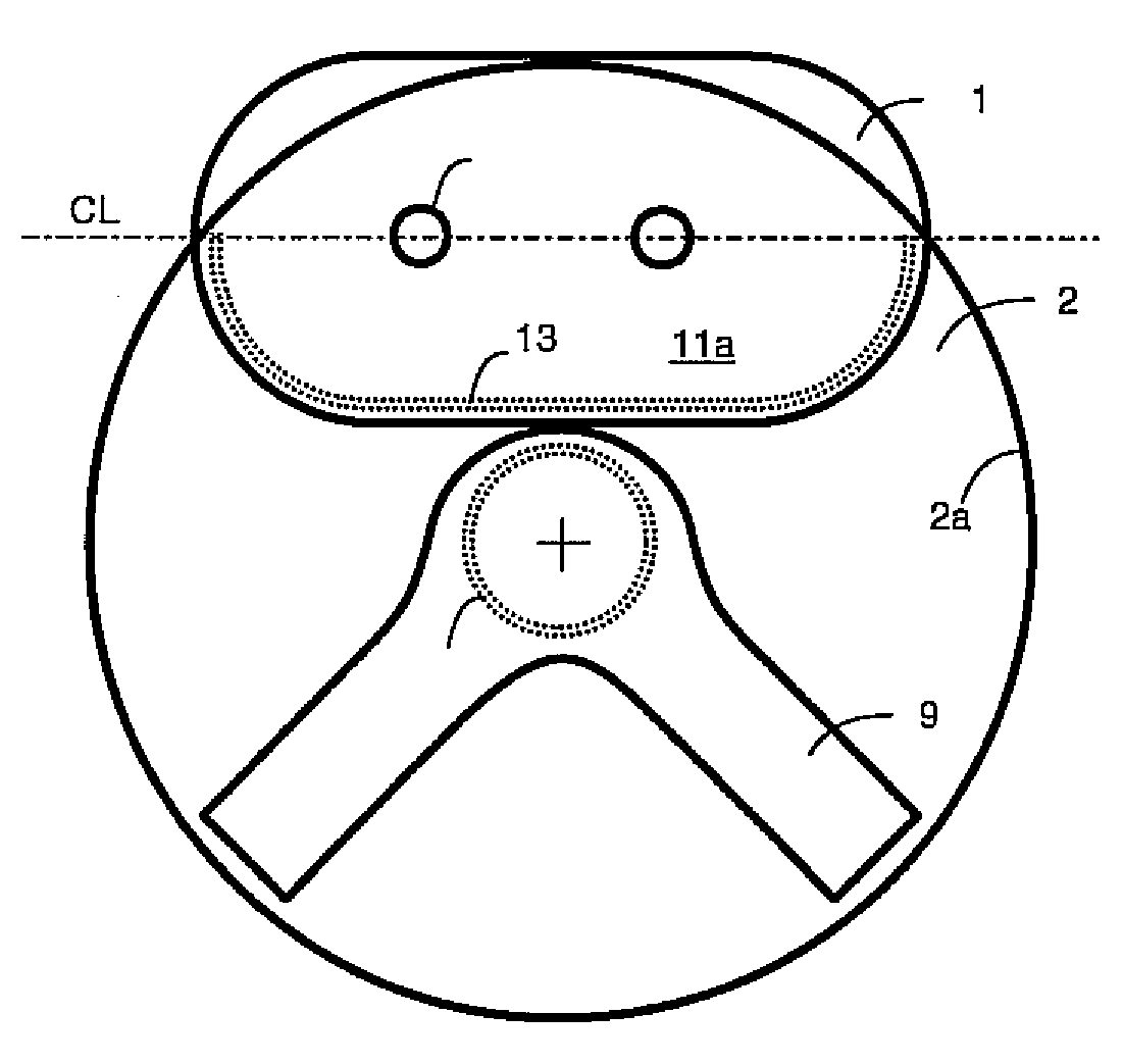
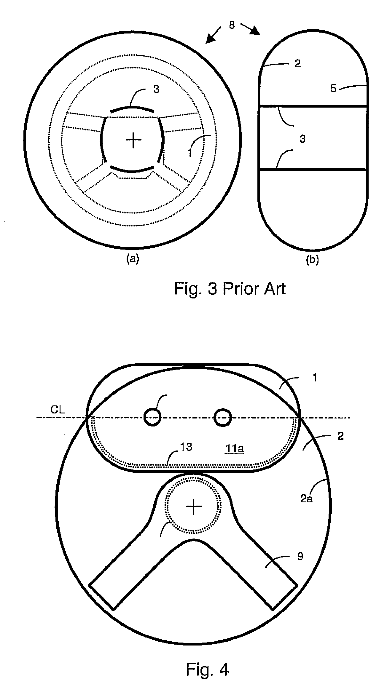
[0043]FIG. 4 shows a circular front panel 2 of the present invention. A lower tether 9 has two straps and is secured, typically by stitching, around the central region 10. An upper tether 11 has a first portion or half 11a, the perimeter 13 of which is secured, typically by stitching, to the front panel 2 above a center point C of the panel 2. The lower tether may be secured to the front panel below the center point C in order to balance with the upper tether. All the stitching is preferably done on a two dimensional flat layout as shown in the figure. For definitional purposes, the front panel may be said to have the center point C at its geometric center and the central region 10 surrounding the center point C. The perimeter 2a of the front panel in this embodiment is equidistant from the center point C, since the front panel is circular. The front panel and corresponding back panel may have other shapes, though circular is typical.

[0044]Preferably, a center line CL of the upper t...

second embodiment

[0051]FIG. 11 shows a front panel 2 of an airbag according to the present invention. In this embodiment, a lower tether 25 has two straps that are stitched around the central region 26 of the front panel. A first portion or half 23a of an upper tether 23 is stitched along its perimeter 24 to the front panel 2 substantially above the center point C. All the stitching is preferably done on a two dimensional flat layout as shown in the figure.

[0052]FIG. 12 shows a rear panel 5 of the second embodiment of the present invention to which the second portion or half 23b of the upper tether 23 is stitched along its perimeter 29 to the rear panel above the inflator hole 7 of the rear panel 5. All the stitching is preferably done on a two dimensional flat layout as shown in the figure.

[0053]FIG. 13 shows an inflated airbag of the second embodiment of the present invention after the front panel shown in FIG. 11 and the rear panel shown in FIG. 12 are stitched together along their perimeters The...

fifth embodiment

[0057]FIG. 17 shows a front panel 2 of the present invention to which a one strap lower tether 48 is secured below the center point of the front panel 2 with a straight stitching seam 49. An upper tether 47 similar to FIG. 4 is also shown. The stitching of the lower tether can be done around the central region as a variation.


PUM


Abstract

A driver airbag includes a front panel facing a driver and an opposite rear panel. Each panel has a central region and a perimeter with a center point being defined at the geometric center of the panel. The perimeters of the front and rear panels are joined to provide an airbag outer shell. A lower tether has a first end secured to the central region of the front panel and a second end being secured to the central region of the rear panel. An upper tether or membrane has a perimeter that is secured to the front and rear panels above the center points thereof. A lower chamber is defined by and below the upper tether and an upper chamber is defined by and above the upper tether. The upper tether has an opening defined therethru for gas to flow from the lower chamber to the upper chamber.

Description

REFERENCE TO RELATED APPLICATIONS[0001]This application claims priority from U.S. Provisional Patent Application Ser. No. 61 / 059,969, filed Dec. 21, 2007 and U.S. Provisional Patent Application Ser. No. 61 / 072,972, filed Jan. 23, 2008, the entire content of both of which are incorporated herein by reference.FIELD OF THE INVENTION[0002]This invention relates to a driver airbag system for use with a motor vehicle, wherein airbag tethers are designed in such a way as to minimize the risk of injuries caused by airbag inflation to an out-of-position occupant while improving in-position occupant protection during serious crashes.BACKGROUND OF THE INVENTION[0003]A dual stage inflator is being used in many passenger vehicles in which the vehicle is required to pass a government's low risk deployment advanced airbag rule. The dual stage inflator is made of two chambers and typically generates two levels of inflator output depending on the severity of crashes. This advanced airbag rule has re...

Claims


Application Information

Patent Timeline
Patent Type & Authority Applications(United States)
IPC IPC(8): B60R21/16
CPCB60R21/233B60R2021/23382B60R2021/23324B60R21/2338
Inventor NAM, JONG SEOPSONG, SEUNG-JAE
Owner CIS TECH LLC
Why Eureka
Try Eureka