Spark plug

a spark plug and plug-in technology, applied in spark plugs, basic electric elements, electric devices, etc., can solve the problems of increasing heat load at operating time, shortening the overall length of the outer electrode, and reducing the breakage strength against vibration, so as to achieve enhanced ignitability, less inhibited, and enhanced ignitability

Inactive Publication Date: 2009-06-25
NGK SPARK PLUG CO LTD
View PDF4 Cites 4 Cited by
  • Summary
  • Abstract
  • Description
  • Claims
  • Application Information

AI Technical Summary

Benefits of technology

[0022]Accordingly, ignitability can be further enhanced. As the area S decreases, the areas of the center electrode leading end portion and the outer electrode which the flame kernel contacts decrease. Therefore, the growth of the flame kernel is less inhibited.
[0023]In a further implementation, a following relationship is satisfied: 0.3 mm≦C≦1.6 mm, where C is defined as a tip length, in mm, of the outer electrode tip from a distal end surface of the outer electrode base member to the distal end surface of the outer electrode tip. As C≧0.3 mm is set, ignitability can be enhanced. Increasing as the tip length C reduces the effect of the outer electrode being at a lower temperature than the flame kernel. On the other hand, as C≦1.6 mm is set, the increasing amount of the spark discharge gap G produced with use effectively suppressed and the durability of the spark plug is enhanced. As the tip length C is shortened, the heat dissipation in the outer electrode (outer electrode tip) improves and the wear amount of the outer electrode tip is suppressed. Therefore, the tip length C is defined in the range 0.3 mm≦C≦1.6 mm, whereby both ignitability and durability are enhanced.
[0024]In a

Problems solved by technology

In the outer electrode, however, since the outer electrode tip is welded, the overall length of the outer electrode tends to become long.
Therefore, the heat load at operating time increases, and the breakage strength against vibration also degrades.
However,

Method used


Image

  • Spark plug
  • Spark plug
  • Spark plug

Examples


first exemplary embodiment

1. First Exemplary Embodiment

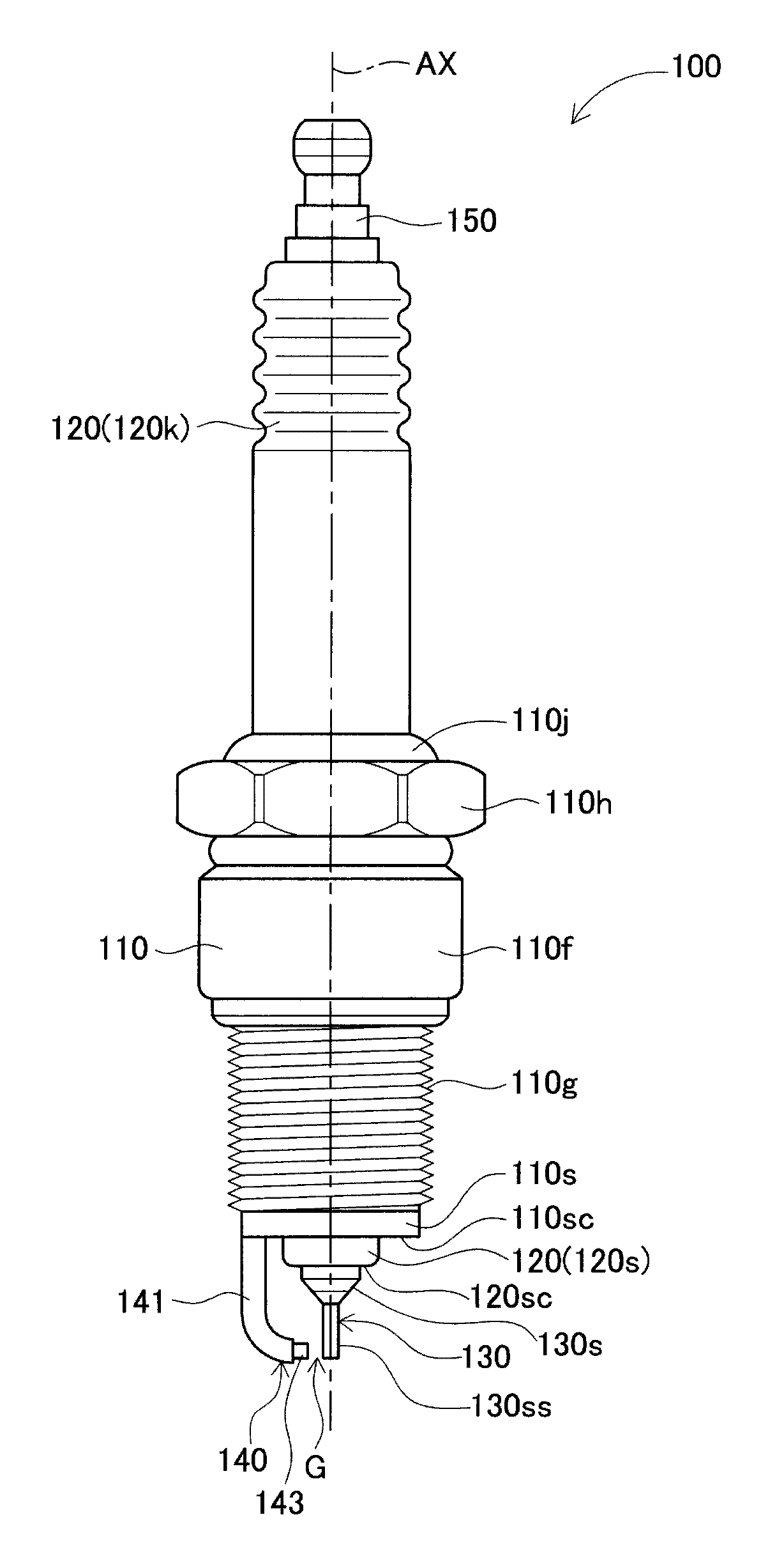
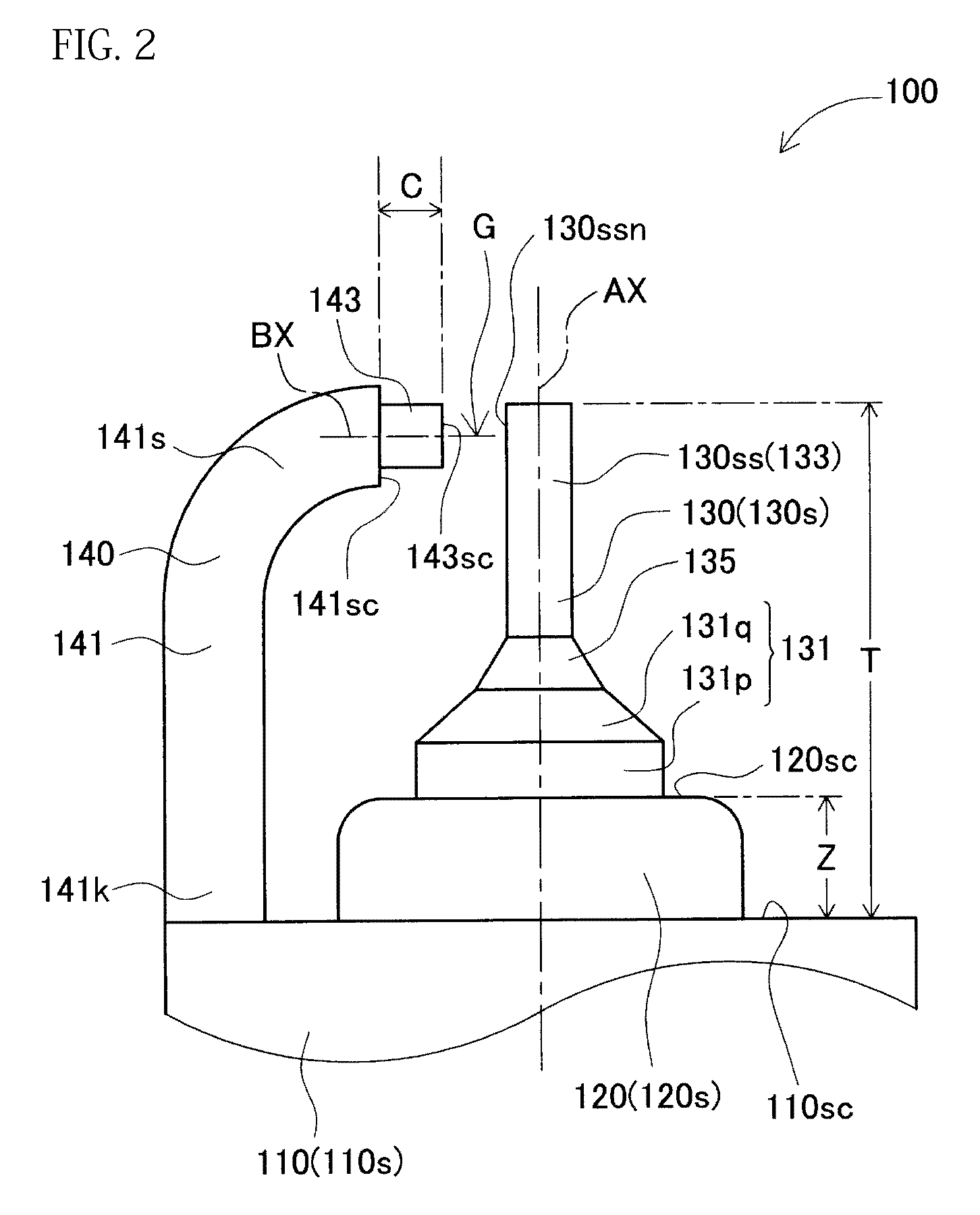
[0056]An exemplary embodiment of the present invention is described with reference to the drawings. However, the present invention should not be construed as being limited thereto. FIG. 1 shows a spark plug 100 according to the exemplary embodiment of the invention. FIG. 2 shows the vicinity of a center electrode 130 and a ground electrode (outer electrode) 140 viewed from a side of the spark plug 100. FIG. 3 shows the center electrode 130, the ground electrode 140 viewed from an axis AX direction leading end side (which will be hereinafter also simply referred to as a “leading end side”) to a base end side. FIG. 4 shows the ground electrode 140 viewed from the radial inside to the radial outside. The spark plug 100 is a spark plug for an internal combustion engine which, in use, is attached to a cylinder head of an engine.

[0057]As shown in FIG. 1, the spark plug 100 includes a cylindrical metal shell 110, a cylindrical insulator 120, the center electrod...

modified embodiments 1 to 3

2. Modified Embodiments 1 to 3

[0163]Next, modified embodiments 1 to 3 of the embodiment described above will be discussed. Portions similar to those of the embodiment described above will not be discussed again in detail. Modified embodiments 1 to 3 differ from the above-described embodiment in that ground electrode base members 241, 341, and 441 differ from the ground electrode base member 141 of the embodiment described above.

[0164]FIG. 25 shows a ground electrode 240 of a spark plug 200 of modified embodiment 1 as viewed from the radial inside toward the radial outside. FIG. 26 shows a ground electrode 340 of a spark plug 300 of modified embodiment 2 as viewed from the radial inside toward the radial outside. FIG. 27 shows a ground electrode 440 of a spark plug 400 of modified embodiment 3 as viewed from the radial inside toward the radial outside.

[0165]In the spark plug 200 of modified embodiment 1, as shown in FIG. 25, a base member distal end surface 241sc of the ground electr...

modified embodiment 4

3. Modified Embodiment 4

[0169]Next, modified embodiment 4 will be described. Portions similar to those of the embodiment and modified embodiments 1 to 3 will not be discussed again in detail. Modified embodiment 4 differs from the embodiment and modified embodiments 1 to 3 in that the joint mode of a ground electrode tip 543 and a ground electrode base member 541 in a ground electrode 540 differs from that in the ground electrode 140, 240, 340, 440 of the embodiment and modified embodiments 1, 2 and 3. FIG. 28 is a side view of a center electrode 130 and the ground electrode 540 of a spark plug 500 according to modified embodiment 4.

[0170]The ground electrode 540 of the spark plug 500 according to modified embodiment 4 includes the ground electrode base member 541 as a base member provided by bending a quadrangular prism member; and the prism-shaped ground electrode tip 543 having a width narrower than that of the ground electrode base member 541.

[0171]The ground electrode base memb...


PUM


Abstract

A spark plug includes an outer electrode including an outer electrode tip of which a distal end surface is spaced from an outer peripheral surface of a leading end portion of a center electrode to define a spark discharge gap. A protruding insulator portion of a cylindrical insulator protrudes at least 1.0 mm from a leading end surface of a cylindrical metal shell. A protruding center electrode portion of the center electrode protrudes at least 3.5 mm from the leading end surface of the cylindrical metal shell. A relationship (θ1+θ2)/2≧75 degrees is satisfied where the angle θ1 is defined as a central angle (degrees) of a first circular sector having a point B1 as a center thereof, and the angle θ2 is an average value (degrees) of the central angles of two second circular sectors having the point B1 as a center thereof.

Description

CROSS-REFERENCE TO RELATED APPLICATIONS[0001]This application is based on and claims priority to Japanese Patent Application No. 2007-326950 filed Dec. 19, 2007, the above application incorporated herein by reference in its entirety.BACKGROUND OF THE INVENTION[0002]1. Field of the Invention[0003]This present invention relates to a spark plug for an internal combustion engine, the spark plug including a cylindrical metal shell, a cylindrical insulator provided in the metal shell, a center electrode provided in the insulator, and an outer electrode including an outer electrode tip welded to an outer electrode base member.[0004]2. Description of Related Art[0005]A spark plug having an outer electrode including an outer electrode base member and a column-shaped outer electrode tip welded to the outer electrode base member is known. This spark plug improves ignitability and durability. In the outer electrode, however, since the outer electrode tip is welded, the overall length of the out...

Claims


Application Information

Patent Timeline
IPC IPC(8): H01T13/20
CPCH01T13/16H01T13/39H01T13/32H01T13/02
Inventor KAMEDA, HIROYUKINAKAYAMA, KATSUTOSHINAGASAWA, SATOSHIYOSHIDA, KAZUMASA
Owner NGK SPARK PLUG CO LTD
Why Eureka
Try Eureka