Front access enclosure

a front access and enclosure technology, applied in the field of improved technology, can solve the problems of increasing the time and effort of users, short connection to the rear connector port, and disconnection of cables, and achieve the effect of quick and efficient neatening the appearance of the enclosure, and great concealment of cables

Inactive Publication Date: 2009-06-25
HUGHES ROBERT M
View PDF11 Cites 19 Cited by
  • Summary
  • Abstract
  • Description
  • Claims
  • Application Information

AI Technical Summary

Benefits of technology

[0008]What is therefore needed is an enclosure and method of construction which will allow a user to fully access virtually all connector ports on a given piece of electronic equipment from the front of the equipment. The enclosure may include a moveable front panel which may or may not support control mechanisms by which to adjust the equipment. The ideal enclosure may be elevated (on feet, for example) such that connector cables from connected devices may be passed beneath the enclosure and routed to peripheral devices from the corresponding connector ports at the front of the enclosure. Alternatively, the enclosure may include one or more channels thro

Problems solved by technology

Over the life of an installation, these connections may need to be accessed from time to time as peripheral devices change or as problems arise that require rearranging connections for debugging and the like.
This is particularly problematic if the equipment in question is located in a small or confined area.
This increases the possibility of accidentally disconnecting cables that are already connected to the equipment, and thus may also increase a user's investment of time and effort by necessitating a search to locat

Method used


Image

  • Front access enclosure
  • Front access enclosure
  • Front access enclosure

Examples


first embodiment

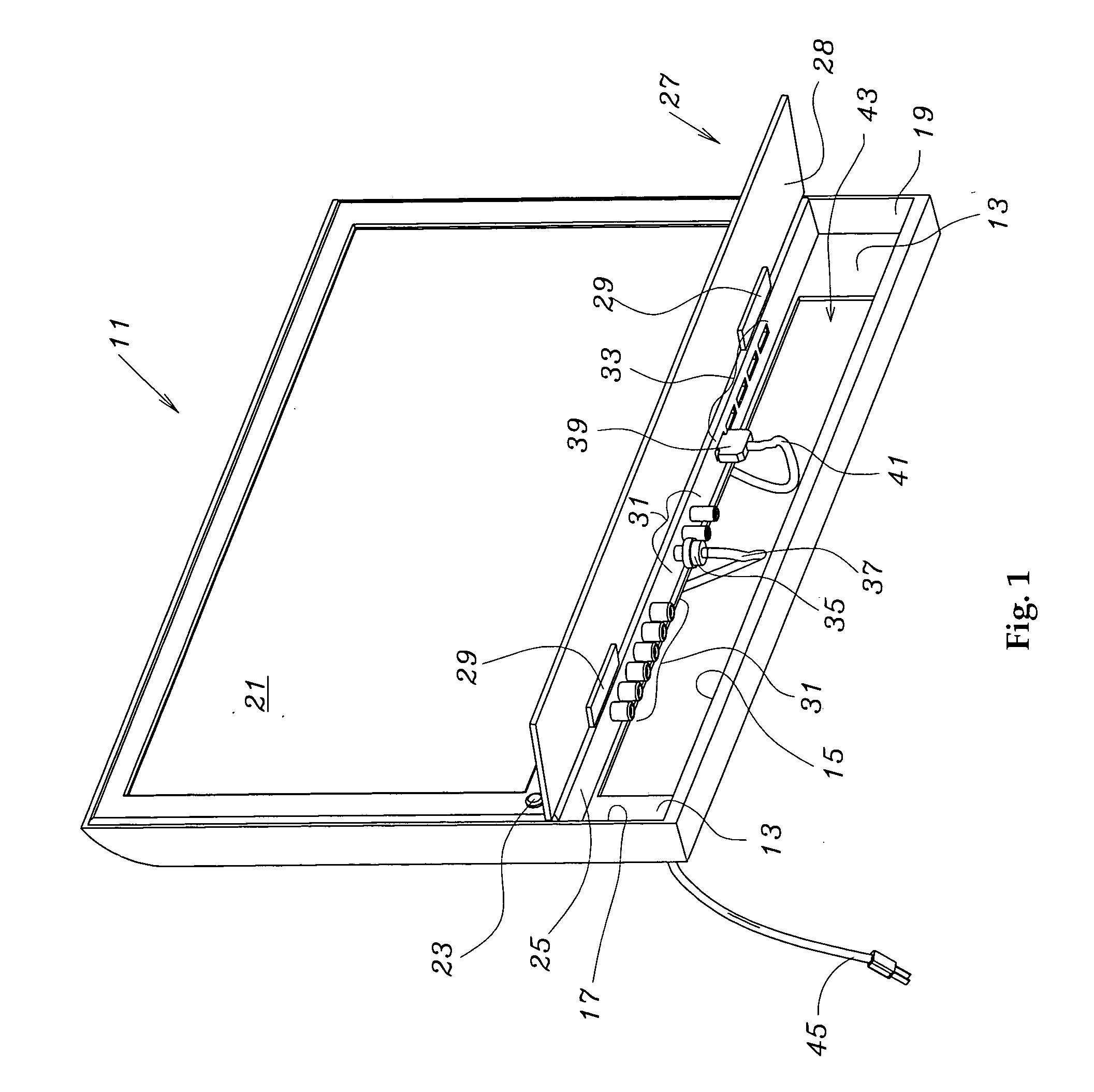
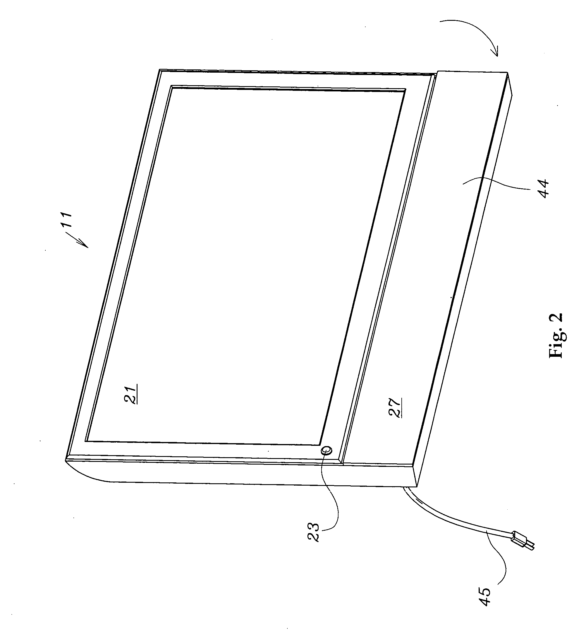
[0017]The description and operation of the invention will be best initiated with reference to FIG. 1, which is a perspective front view of the present invention and illustrates a shallow enclosure 11 which may include a rear wall 13, a floor 15, a left side wall 17, and a right side wall 19. Enclosure 11 may include an output device such as screen 21, a power button 23, and a horizontal connector strip 25 accessible through a moveable front access panel 27 attached to enclosure 11. Moveable front access panel 27 is shown in an open position, making rear surface 28 and hinges 29 visible.

[0018]Horizontal connector strip 25 may have a plurality of male connector ports 31 and female connector ports 33 located thereon by which to connect output device 21 either to other peripheral devices that serve as inputs or outputs, or to a central control unit. Although horizontal connector strip 25 is illustrated as having primarily male and female connector ports 31 and 33, respectively, horizont...

second embodiment

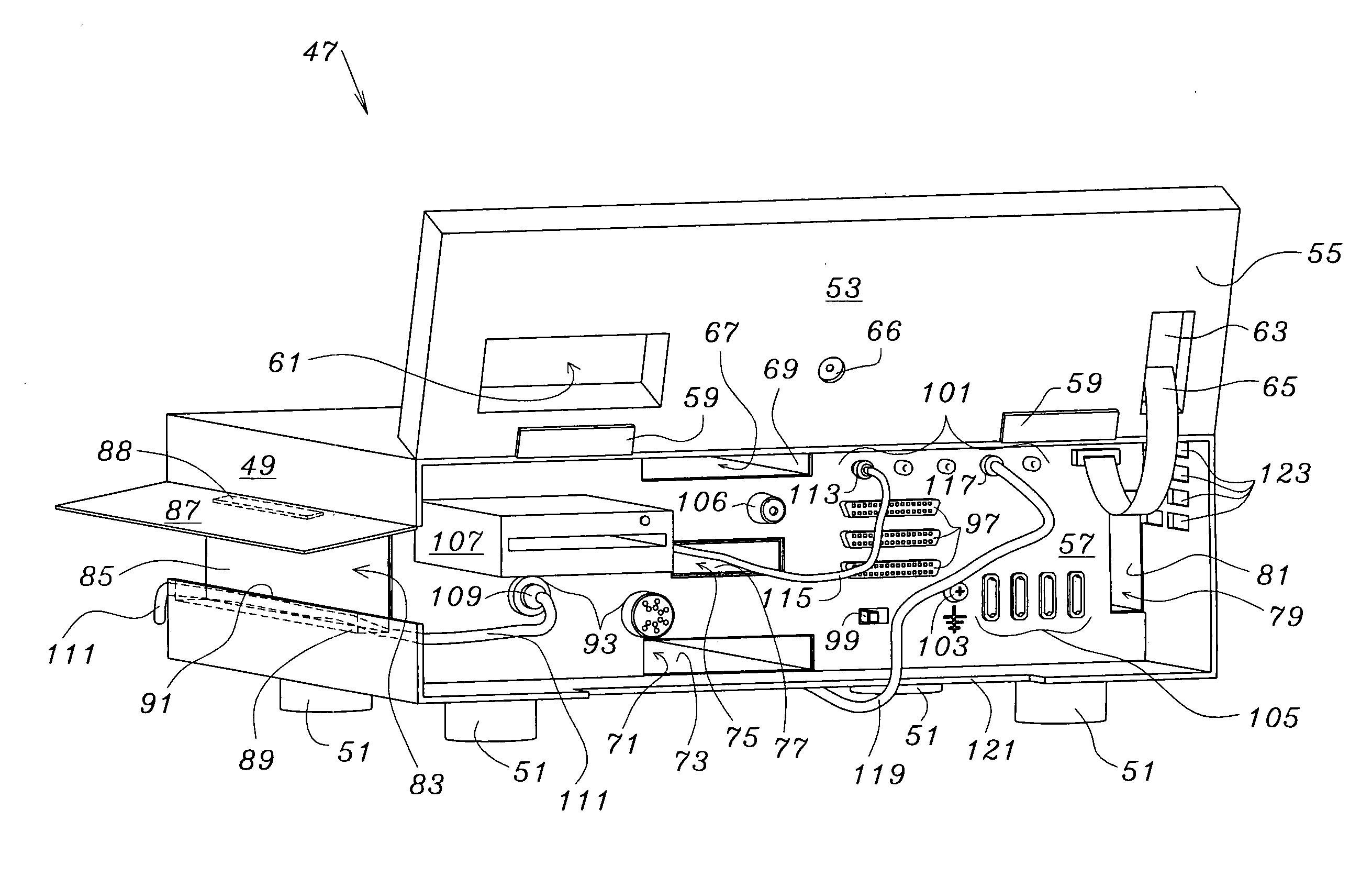
[0024]FIG. 4 is a perspective front view of the present invention and illustrates a deeper enclosure 47 and which includes a housing 49 equipped with adjustable feet 51 and a moveable front panel 53. Moveable front access panel 53 is shown in an open position so that its rear surface 55 is visible, as is recessed connector panel 57 which is normally concealed by moveable front access panel 53 when moveable front access panel 53 is in a closed position.

[0025]Moveable front access panel 53 is illustrated as having hinges 59 by which it is attached to housing 49 of enclosure 47. Moveable front access panel 53 is shown as being hinged at the top, although it could conceivably be hinged at the bottom or at the left or right sides. Moreover, moveable front access panel 53 could be completely detachable from housing49 to provide unrestricted access to recessed connector panel 57 without the worry of damaging or stressing hinges 59 during access. Finally, although moveable front access pane...


PUM


Abstract

An enclosure and method of construction for use with electronic devices such as computers, amplifiers, switching systems, receivers, video monitors, and televisions, allows a user to access virtually all connector ports on a given piece of equipment from the front of the equipment by displacing a moveable front accessible control panel which supports control mechanisms by which to regulate the equipment. The ideal enclosure may be elevated on adjustable feet such that connector cables from connected peripheral devices may be routed beneath the enclosure to corresponding connector ports at the front of the enclosure. Alternatively, the enclosure may include one or more channels through which connector cables may be passed for greater concealment. Channels may be fixed, may include moveable panels for greater access, or may be completely removable for more easily accessing internal components of the enclosure.

Description

FIELD OF THE INVENTION[0001]The present invention relates to improved technology in the field of enclosures for electronic equipment, and more particularly to an enclosure and method of construction which enables a user frontal access to virtually all connector ports on a given piece of equipment via displacement of a movable front panel, and which also optionally allows a user to quickly and concealably route connector cables from connected devices to the front of the enclosure by routing the cables either beneath the enclosure or, for greater concealment, through one or more channels within the enclosure.BACKGROUND OF THE INVENTION[0002]Currently available electronic devices such as computers, amplifiers, switching systems, receivers, televisions, and various other kinds of equipment may support a limited number of connector ports mounted on a front face for ease of accessibility. Such ports are usually directed toward temporary applications, and their functionality range is gener...

Claims


Application Information

Patent Timeline
IPC IPC(8): H05K5/00
CPCH05K5/0247
Inventor HUGHES, ROBERT M.
Owner HUGHES ROBERT M
Why Eureka
Try Eureka