Geometric parameter measurement of an imaging device

a technology of geometric parameters and imaging devices, applied in the field of camera calibration, can solve the problems of unsuitable techniques, difficult to remove ambiguities along the third dimension, and limit the accuracy of characteristics intended to be measured by the char

Active Publication Date: 2009-06-25
CANON KK
View PDF10 Cites 46 Cited by
  • Summary
  • Abstract
  • Description
  • Claims
  • Application Information

AI Technical Summary

Benefits of technology

[0011]It is an object of the present invention to substantially overcome, or at least ameliorate, one or more disadvantages of existing approaches.

Problems solved by technology

In practice, attaining such ideal alignment, or measuring deviations from the ideal alignment in an existing setup, can be achieved only to a certain accuracy, which imposes limits on the accuracy of the characteristics intended to be measured by the chart.
In view of these non-ideal alignment issues, testing is a three-dimensional (3D) problem rather than a relatively simpler two-dimensional (2D) problem.
While the position of visible features in two dimensions is well defined by images, removing ambiguities in the position along the third dimension is difficult.
These techniques are unsuitable for use in the case when the object to be imaged is necessarily planar and oriented close to perpendicular to the optical axis.
This is not adequate to calculate the geometric parameters of the system to the accuracy that is required for certain system performance measurements.
To partially compensate for the limited spatial resolution of feature detection, many such features are often used, covering much of the surface area of the object, although this still results in limited accuracy in the derived geometric parameters.

Method used


Image

  • Geometric parameter measurement of an imaging device
  • Geometric parameter measurement of an imaging device
  • Geometric parameter measurement of an imaging device

Examples


Embodiment Construction

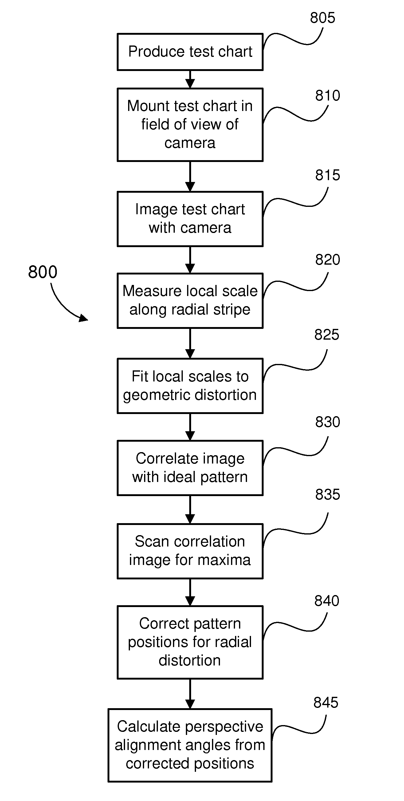
[0037]For applications such as making quantitative measurements of image quality, it is desirable to image a planar test chart with an imaging system, while either:[0038]having the test chart in a precisely specified geometric configuration with respect to the imaging system, or[0039]being able to precisely measure the geometric configuration of the test chart with respect to the imaging system.

[0040]If the test chart can be set up in a specified configuration (for example, an accepted standard) the measurements of image quality can be characterised properly as being measured for that configuration. On the other hand, if the configuration of the test chart is not precisely controlled, but can be measured accurately while making the image quality measurements, then those quality measurements can be properly qualified in terms of the geometric alignment. It may also be possible to interpolate or extrapolate the image quality measurements to produce good estimates of image quality for ...


PUM


Abstract

Disclosed is a method of determining at least one three-dimensional (3D) geometric parameter of an imaging device. A two-dimensional (2D) target image is provided having a plurality of alignment patterns. The target image is imaged with an imaging device to form a captured image. At least one pattern of the captured image is compared with a corresponding pattern of the target image. From the comparison, the geometric parameter of the imaging device is then determined. The alignment patterns include at least one of (i) one or more patterns comprising a 2D scale and rotation invariant basis function, (ii) one or more patterns comprising a 1D scale invariant basis function, and (iii) one or more patterns having a plurality of grey levels and comprising a plurality of superimposed sinusoidal patterns, the plurality of sinusoidal patterns having a plurality of predetermined discrete orientations. Also disclosed is a two-dimensional test chart for use in testing an imaging device, the test chart comprising a plurality of alignment patterns, at least one of said alignment patterns including one of those patterns mentioned above.

Description

CROSS-REFERENCE TO RELATED PATENT APPLICATIONS[0001]This application claims the right of priority under 35 U.S.C. § 119 based on Australian Patent Application No. 2007254627, filed Dec. 21, 2007, which is incorporated by reference herein in its entirety as if fully set forth herein.TECHNICAL FIELD[0002]The current invention relates to camera calibration and, in particular, to obtaining geometric parameters of an imaging system.BACKGROUND ART[0003]It is often desirable to capture images of a planar test chart containing patterns designed for the measurement of characteristics of the imaging system. For many purposes, the ideal configuration is to have the test chart oriented perpendicular to the optical axis of the imaging system. In practice, attaining such ideal alignment, or measuring deviations from the ideal alignment in an existing setup, can be achieved only to a certain accuracy, which imposes limits on the accuracy of the characteristics intended to be measured by the chart....

Claims


Application Information

Patent Timeline
Patent Type & Authority Applications(United States)
IPC IPC(8): G06K9/00H04N17/00H04N1/00
CPCG06K9/3216H04N17/002H04N1/00827G06T5/006G06V10/245
Inventor MORGAN-MAR, DAVIDHARDY, STEPHEN JAMESARNISON, MATTHEW R.LARKIN, KIERAN GERARDDELLER, CHRISTINE ANNE
Owner CANON KK
Why Eureka
Try Eureka