Platen incorporating an RFID coupling device

a platen and coupling device technology, applied in the field of platens, can solve the problems of increasing system complexity and cost, affecting the efficiency of printing, so as to achieve the effect of effectively receiving signals from devices, effectively communicating with other devices, and effectively transmitting signals to devices

Active Publication Date: 2009-06-25
ZEBRA TECH CORP
View PDF72 Cites 9 Cited by
  • Summary
  • Abstract
  • Description
  • Claims
  • Application Information

AI Technical Summary

Benefits of technology

[0014]In some embodiments, the interrogator and the media processing component can be in communication with a control system that is configured to correlate a media processing operation of the media processing component with a signal emitted by and / or received by the electromagnetic coupler. In another embodiment, the processing area may be substantially coincident with a communication area established at least in part by the interrogator. The communication area refers to the area within which the interrogator can effectively communicate with other devices (i.e., can effectively transmit signals to devices located within the communication area and / or can effectively receive signals from devices located within the communication area). The dimensions of the communication area may be affected by aspects of the interrogator, such as the structure and geometry of the electromagnetic coupler and the amount of power supplied thereto, and also by aspects of the respective communication element with which the interrogator is communicating (e.g., the size, shape, structure, orientation with respect to the interrogator, etc.) and aspects of the surrounding environment. Overall, the dimensions of the communication area will depend on the specific communication taking place between the interrogator and a respective communication element (a “communication event”), and may change from one communication event to another. The control system may, in some cases, be at least partially integrated with or otherwise include the functionality of the interrogator.

Problems solved by technology

Problems can occur when interrogating multiple adjacent transponders, regardless of whether the transponders are powered by an on-board direct current (DC) power supply or by a RF field generated by a separate RFID interrogator.
This simultaneous activation of multiple transponders may lead to communication (i.e., read and write) errors because each of the multiple transponders may attempt communication with the transceiver at the same time.
However, such collision management techniques tend to increase system complexity and cost, and may also result in delayed response.
Furthermore, such techniques are often “blind” in that they cannot locate a given transponder or more specifically recognize the position of a transponder within the interrogating RF electromagnetic field.
Unfortunately, RF-shielded housings add cost and complexity to a system and limit the type (e.g., size) of transponders that can be processed by the system.
Furthermore, many systems in which RFID tag interrogation might be employed are limited with regard to space or weight and, thus, cannot accommodate such shielded housings.
The challenge of avoiding multiple transponder activation may be especially acute in the case of RFID printer-encoders.
The close proximity of the transponders to each other during processing makes targeting a particular transponder for encoding purposes problematic.
Moreover, the space, cost, and weight restrictions associated with such devices, among other factors, make collision management techniques or shielding components for alleviating multiple transponder activation less than desirable.
Further, “blind” collisions management techniques could lead to uncorrelated printing and data encoding for a given RF label.

Method used


Image

  • Platen incorporating an RFID coupling device
  • Platen incorporating an RFID coupling device
  • Platen incorporating an RFID coupling device

Examples


Embodiment Construction

[0031]The present inventions now will be described more fully hereinafter with reference to the accompanying drawings, in which some, but not all embodiments of the inventions are shown. Indeed, these inventions may be embodied in many different forms and should not be construed as limited to the embodiments set forth herein; rather, these embodiments are provided so that this disclosure will satisfy applicable legal requirements. Like numbers refer to like elements throughout.

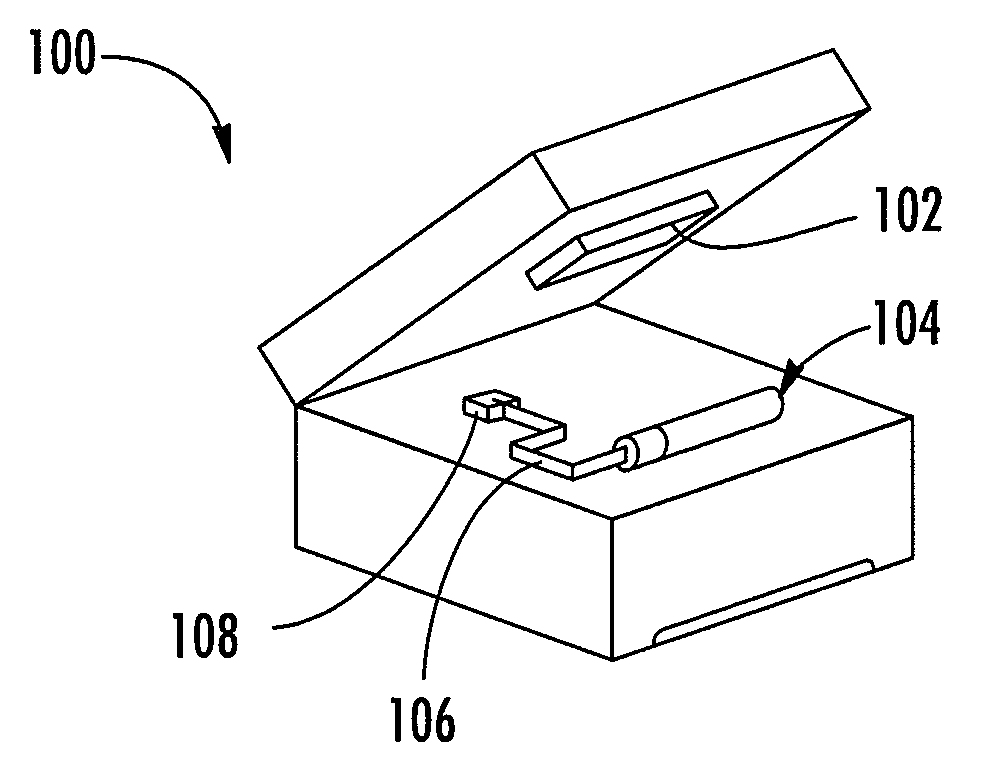
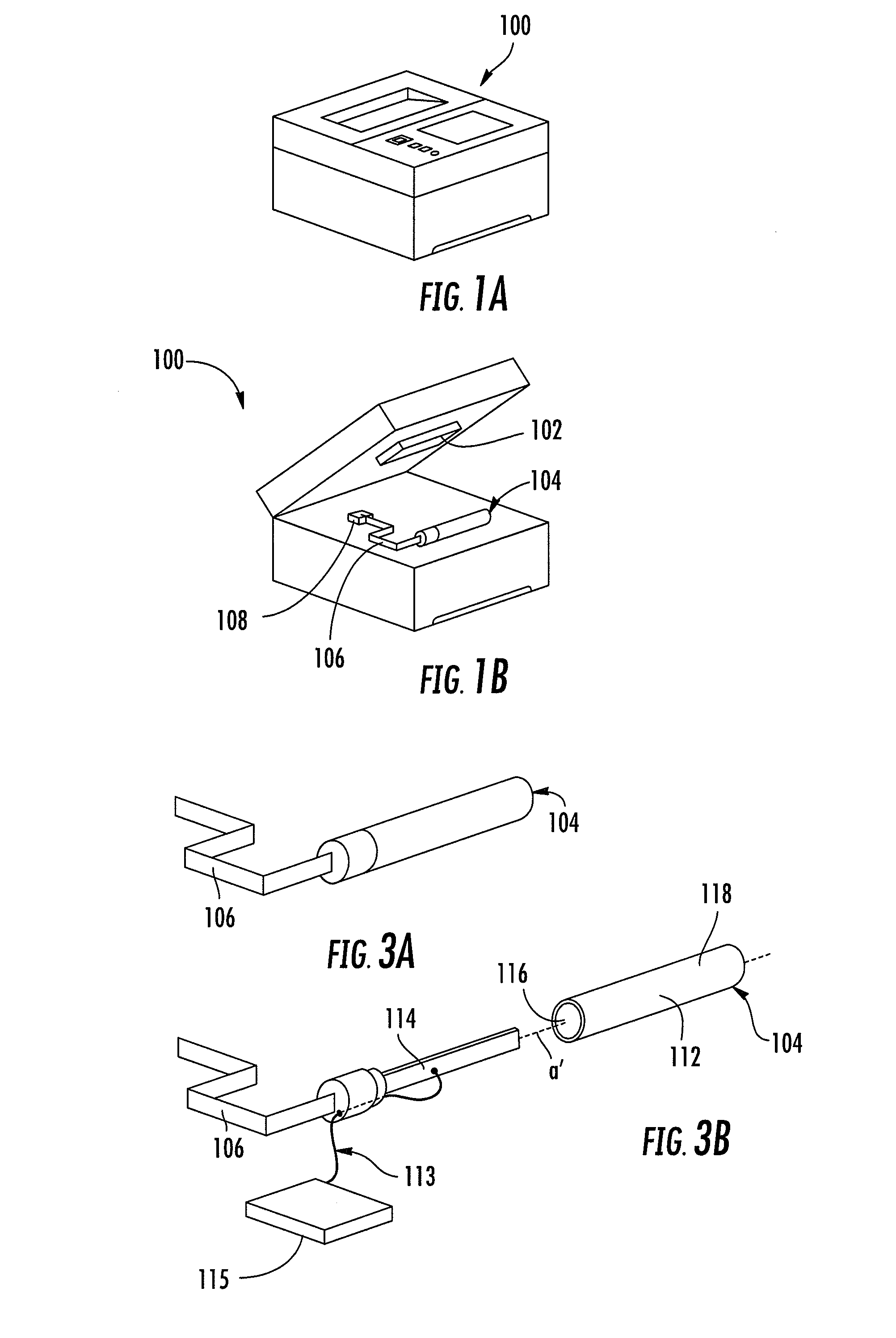
[0032]Referring to FIGS. 1A and 1B, therein are shown views of a media processing apparatus configured in accordance with an exemplary embodiment. In this case, the depicted media processing apparatus is a printer 100, although in other embodiments, the media processing apparatus may be any device capable of receiving and processing / modifying media, including, for example, a copier, a label machine, a fax machine, a drill, milling machine, lathe, or some other cutting or engraving device, an automatic painting...


PUM


Abstract

Provided is an apparatus, such as a printer, that includes a media modification component, such as a printhead, and an opposing member, such as a platen. The opposing member opposes the media modification component and is configured to manipulate media for modification by the media modification component. An RFID interrogator including an electromagnetic coupler, such as an antenna, can be associated with the opposing member, for example, by disposing the electromagnetic coupler within a bore defined by the opposing member. In some embodiments, the interrogator and the media modification component can be in communication with a control system that can be configured to correlate a media modification operation of the media modification component with either or both of a signal emitted by or received by the electromagnetic coupler.

Description

BACKGROUND[0001]1. Field of the Invention[0002]Embodiments of the present invention relate to printers and, more particularly, to printers including platens that incorporate electromagnetic couplers for coupling to radio frequency identification transponders.[0003]2. Background Information[0004]Radio frequency identification (RFID) transponders or tags, either active or passive, are typically used with an RFID interrogator or similar device for communicating information back and forth. In operation, the interrogator exposes the transponder to a radio frequency (RF) electromagnetic field or signal. In the case of a passive ultrahigh frequency (UHF) transponder, the RF electromagnetic field energizes the transponder and thereby prompts the transponder to respond to the transceiver by re-radiating the received signal back and modulating the field in a well-known technique called “backscattering.” In the case of a passive high frequency (HF) transponder, the transponder modulates the im...

Claims


Application Information

Patent Timeline
Patent Type & Authority Applications(United States)
IPC IPC(8): B41J11/44
CPCB41J11/02B41J3/44
Inventor TSIRLINE, BORISKOVANKO, STEVEN R.ZWIER, TOMTORCHALSKI, KARL
Owner ZEBRA TECH CORP
Why Eureka
Try Eureka