High lift transonic turbine blade

a turbine blade and high-lift technology, applied in the field of turbine blades, can solve the problems of reducing blade efficiency and important inefficiencies due to shock wave losses

Inactive Publication Date: 2009-06-25
RAYTHEON TECH CORP
View PDF99 Cites 24 Cited by
  • Summary
  • Abstract
  • Description
  • Claims
  • Application Information

AI Technical Summary

Problems solved by technology

In these situations inefficiencies due to shock wave losses are important.
However, the remaining blades must then extract more work, the lift or loading of the blade, from the fluid streams passing thereby which tends to reduce blade efficiency.

Method used


Image

  • High lift transonic turbine blade
  • High lift transonic turbine blade
  • High lift transonic turbine blade

Examples


Embodiment Construction

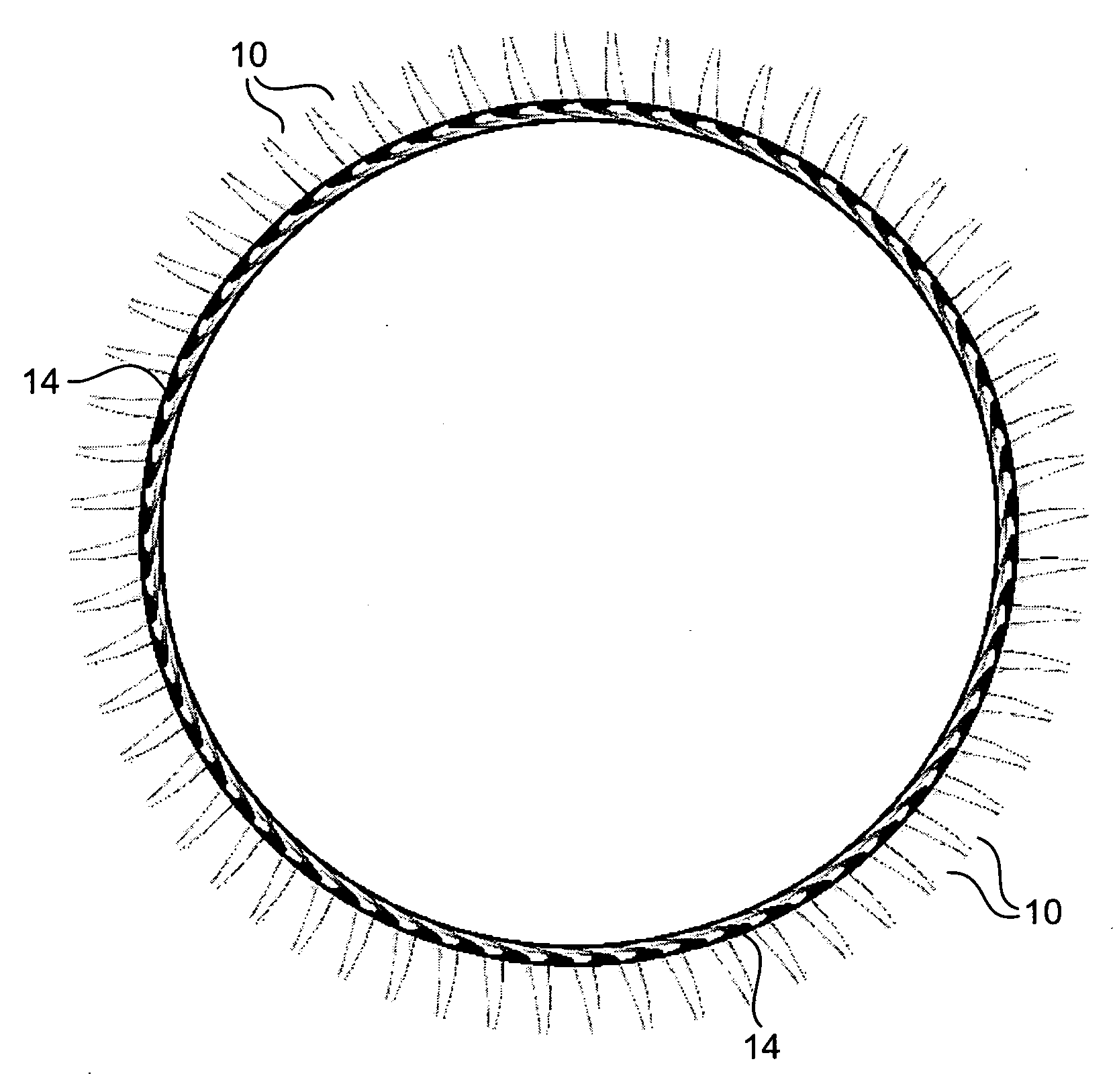
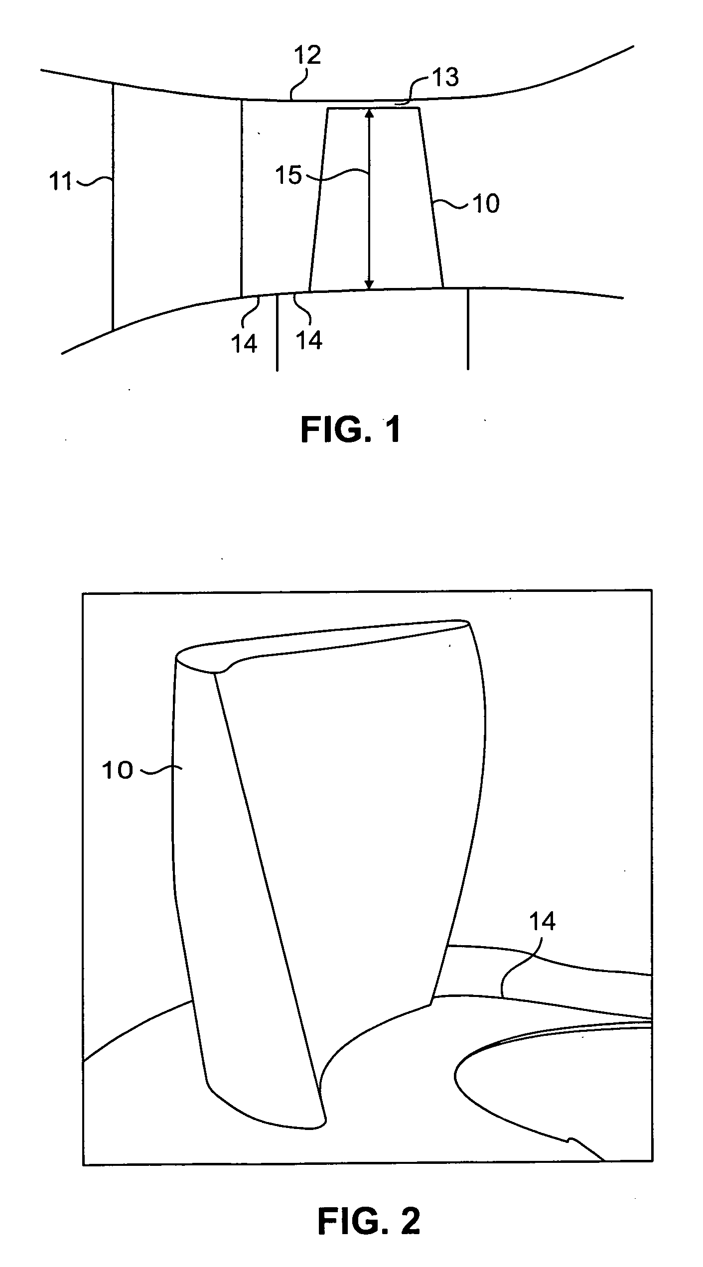
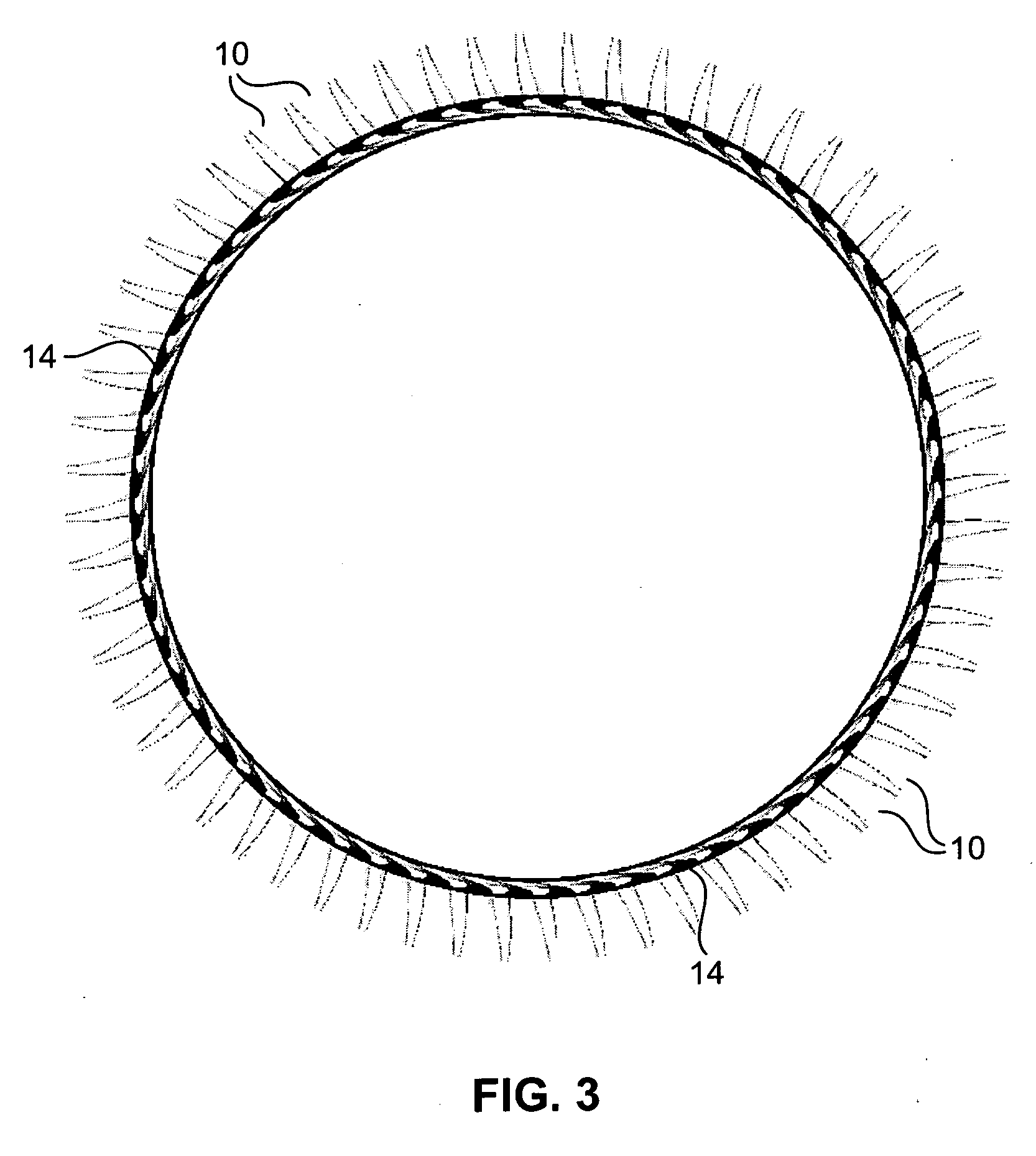
[0013]FIG. 1 shows the relationship of a blade, 10, mounted on a rotatable platform extending about an unseen turbine shaft adjacent a fluid guide vane, 11. Above them is shown the edge of the engine wall limiting the outer extent of the fluid flow path past blade 10 and vane 11, that is, forming the outer diameter, 12, of this fluid flow passage containing blade 10 and vane 11. Rotatable blade 10 has a gap, 13, between the tip of that blade and outer diameter 12 but vane 11 is fixed to the structure providing this fluid flow passageway outer diameter as well as to the structure supporting it from below. That vane supporting structure and the platform on which blade 10 is mounted together limit the inner extent of the fluid flow path past blade 10 and vane 11, that is, forming the inner diameter, 12, of this fluid flow passage containing blade 10 and vane 11. Blade 10 is shown having an outward extent from the platform on which it is mounted to its tip designated as its span, 15.

[00...


PUM


Abstract

A turbine blade system including a blade airfoil having an airfoil shape with the blade airfoil having a nominal profile substantially in accordance with normalized Cartesian coordinate values Z set forth in a table 1 below and which values are dimensionless values that are convertible to corresponding absolute distance values that define nominal airfoil profile sections and which, when joined smoothly with adjacent ones thereof, form a complete nominal airfoil shape that is substantially matched by the airfoil shape of the blade airfoil. This blade airfoil can be supported on a ring platform having a support surface with a support surface shape in the vicinity of the location at which that blade airfoil is supported thereon formed in a similar manner.

Description

BACKGROUND OF THE INVENTION[0001]The present invention relates to turbine blades for turbomachinery such as gas turbine engines and, more particularly, to improved geometrical shapes for such blades and the platform from which they extend.[0002]Turbine blades are mounted circumferentially on an inner diameter platform about a turbine shaft to allow rotation thereof in streams of working medium fluids to extract energy and work therefrom as those fluids flow around and past such blades through the flow passages between them. Such flows can be transonic in accelerating from below the speed of sound coming into the blade region to being above the speed of sound in the exit region. In these situations inefficiencies due to shock wave losses are important.[0003]Blade airfoil surface profiles and the geometry of the airfoil and the platform on which the blade is mounted become very important in achieving high efficiencies. In addition, a blade design to be suitable must minimize the penal...

Claims


Application Information

Patent Timeline
Patent Type & Authority Applications(United States)
IPC IPC(8): F01D5/02F01D5/14
CPCF01D5/141F05D2240/80F05D2250/74
Inventor AGGARWALA, ANDREW S.GACEK, RICHARD E.STAUBACH, JOSEPH B.
Owner RAYTHEON TECH CORP
Why Eureka
Try Eureka