Dental composite shaping burs

a technology of dental composites and burs, which is applied in the field of dental tools, can solve the problems of limited ability of dental composite burs of u.s. patent no. 6,186,788 to achieve the detail of the final surface that can be obtained, and none of the prior art is well-suited to performing detailed sculpting of the finished surface of dental composites

Inactive Publication Date: 2009-06-25
BHR PROJECT
View PDF6 Cites 7 Cited by
  • Summary
  • Abstract
  • Description
  • Claims
  • Application Information

AI Technical Summary

Benefits of technology

[0019]It is a further object to provide a tool that is capable of constructing irregular occlusal surfaces that form a superior match to the occlusal face of opposing teeth.

Problems solved by technology

However none of the prior art is well-suited for performing detailed sculpting of the finished surface of dental composites used in repairing teeth with dental caries.
Thus the usefulness of the tool is generally limited to prosthetic dentures.
Additionally, the burs of U.S. Pat. No. 6,186,788 of are limited capability in the detail of the final surface that can be obtained, where only approximately straight grooves or cusps many be crafted.
Thus for example, where a prosthetic denture is used in opposition to a natural tooth, with its curved and irregular cusps and grooves, the fit and comfort of the resulting bite is not optimal.

Method used


Image

  • Dental composite shaping burs
  • Dental composite shaping burs
  • Dental composite shaping burs

Examples


Embodiment Construction

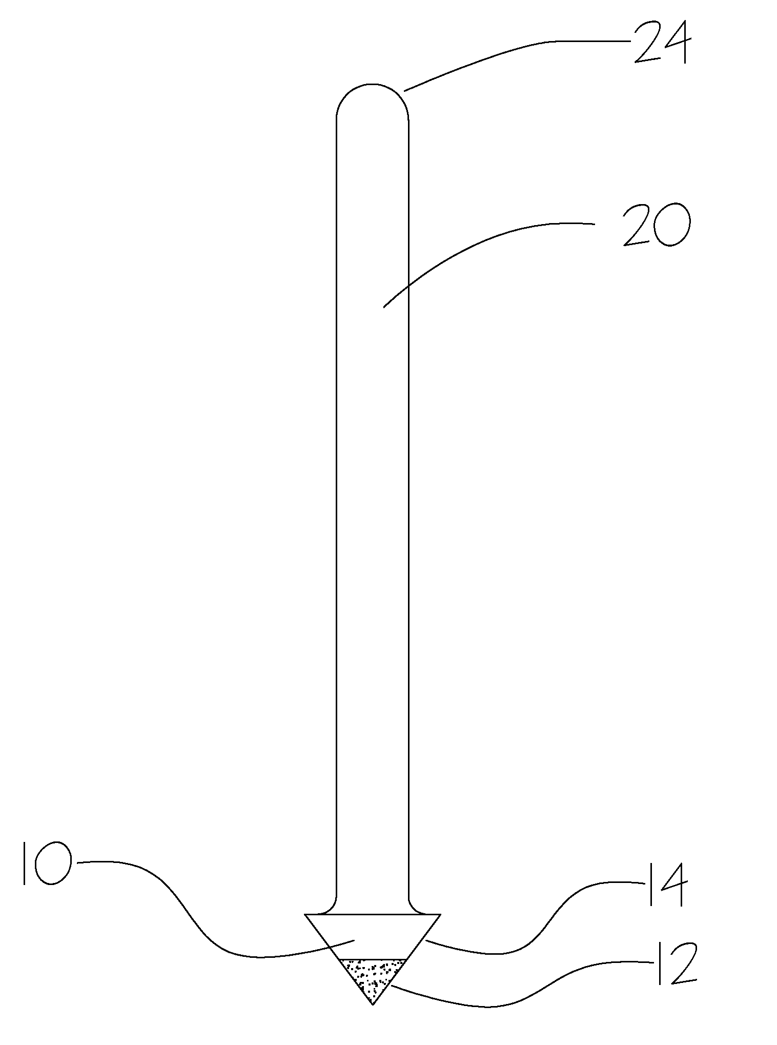
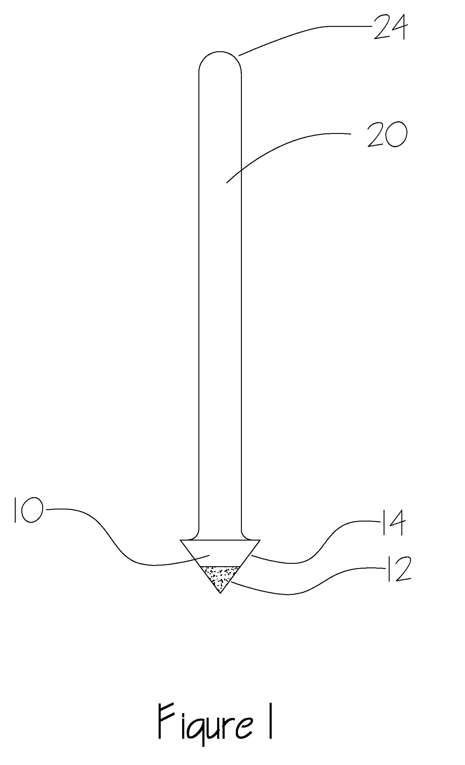
[0026]FIG. 1 illustrates one embodiment of the present invention comprising a conically shaped bur 10 attached coaxially to the distal end of a cylindrical shaft 20. In this embodiment the tip of the cone includes an abrasive surface 12 and the basal edge or periphery of the conical surface 14 presents a smooth surface suitable for limiting the overall penetration of the bur. This embodiment also includes a proximal shaft end 24 formed for commonly used power drive handsets or drills designed to operate at high speeds. This embodiment is useful for crafting grooves or fossae of the occlusal surfaces of the tooth.

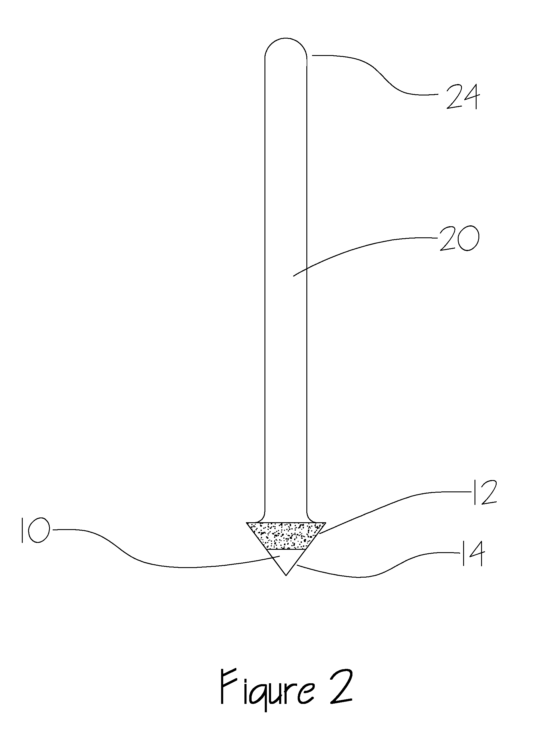
[0027]In an alternate embodiment as shown in FIG. 2, the tip portion of the conical bur 10 presents the smooth limiting surface 14, and the peripheral outward basal edges have the abrasive surface 12. This embodiment also includes a proximal shaft end 24 suitable for commonly used power drive handsets or drills designed to operate at high speeds. This embodiment of the prese...


PUM


Abstract

A system of conically shaped dental burs mounted on the end of cylindrical shafts is disclosed. In one embodiment, the tip of the cone presents an abrasive surface, while the basal edge of the conical surface presents a smooth surface useful for limiting the overall penetration of the bur. This may be used for crafting grooves or fossae on dental surfaces. In an alternate embodiment the tip portion of the conical bur presents the smooth limiting surface, and the peripheral edges are abrasive, so that this bur is useful for reducing cusps or ridges. The burs are used with the axis of rotation perpendicular to the plane of the tooth. They used alternately by the dental practitioner in the detailed sculpting of dental composite fillings. The shaft portion incorporates finished shapes commonly used for either high speed or low speed bur drive systems.

Description

CROSS REFERENCE TO RELATED APPLICATIONS[0001]Not applicable.STATEMENT REGARDING FEDERALLY SPONSORED RESEARCH OR DEVELOPMENT[0002]Not applicable.REFERENCE TO MICROFICHE APPENDIX[0003]Not applicable.FIELD OF THE INVENTION[0004]The present invention relates to the field of dental tools, and more specifically to the field of dental grinding burs. The present invention specifically relates to a bur suitable for constructing the complex detailed surface of the occlusal face of a tooth where the natural surface has been replaced by dental composite filling.BACKGROUND OF THE INVENTION[0005]In the practice of the dental arts, grinding bits or burs are used with power drive accessories to perform different tasks in reducing teeth for veneers or crowns, for removing decay, or for performing root canals. Other needs include boring natural teeth for the insertion of posts for securing crowns or of bone for installing implants. There generally exists a need not to grind too deeply into the tooth ...

Claims


Application Information

Patent Timeline
Patent Type & Authority Applications(United States)
IPC IPC(8): A61C3/06
CPCA61C3/06
Inventor HAROUNI, GEORGE
Owner BHR PROJECT
Why Eureka
Try Eureka