
Voltage detecting device

Active Publication Date: 2009-06-25
YAZAKI CORP
View PDF3 Cites 17 Cited by
  • Summary
  • Abstract
  • Description
  • Claims
  • Application Information

AI Technical Summary

Benefits of technology

[0019]According to the present invention, an address of respective voltage detecting unit can be set by communication through the first communication line. Furthermore, although the power source level of respective voltage detecting unit differ, the address of respective voltage detecting unit can be set.
[0020]According to the present invention, an address number of voltage detecting unit, which is farthest away from the control device, can be automatically transmitted to the control device. Thereby, it is not required to set the address number of voltage detecting unit being farthest away from the control device.
[0021]According to the present invention, the voltage detecting device of the present invention can control ON / OFF of power source against the voltage detecting unit by the control device.
[0022]According to the present invention, action for setting an address can be automatically performed by supplying power source without an external terminal which makes the voltage detecting unit start the action for setting the address. As a result, a cost can be reduced.

Problems solved by technology

Furthermore, since a lot of external terminals are required by the number of address, it causes an increasing manufacturing cost.
Thereby, when the electrical potential of power source in the respective voltage detection IC is not equalized, the conventional method can not be used with a voltage detecting device.

Method used


Image

  • Voltage detecting device
  • Voltage detecting device
  • Voltage detecting device

Examples


Embodiment Construction

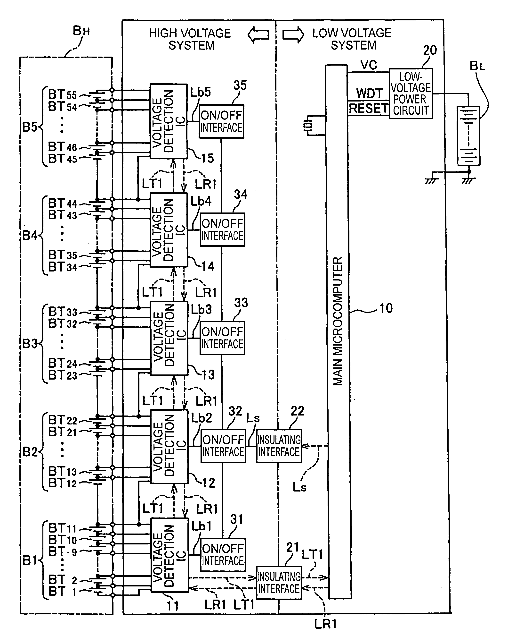
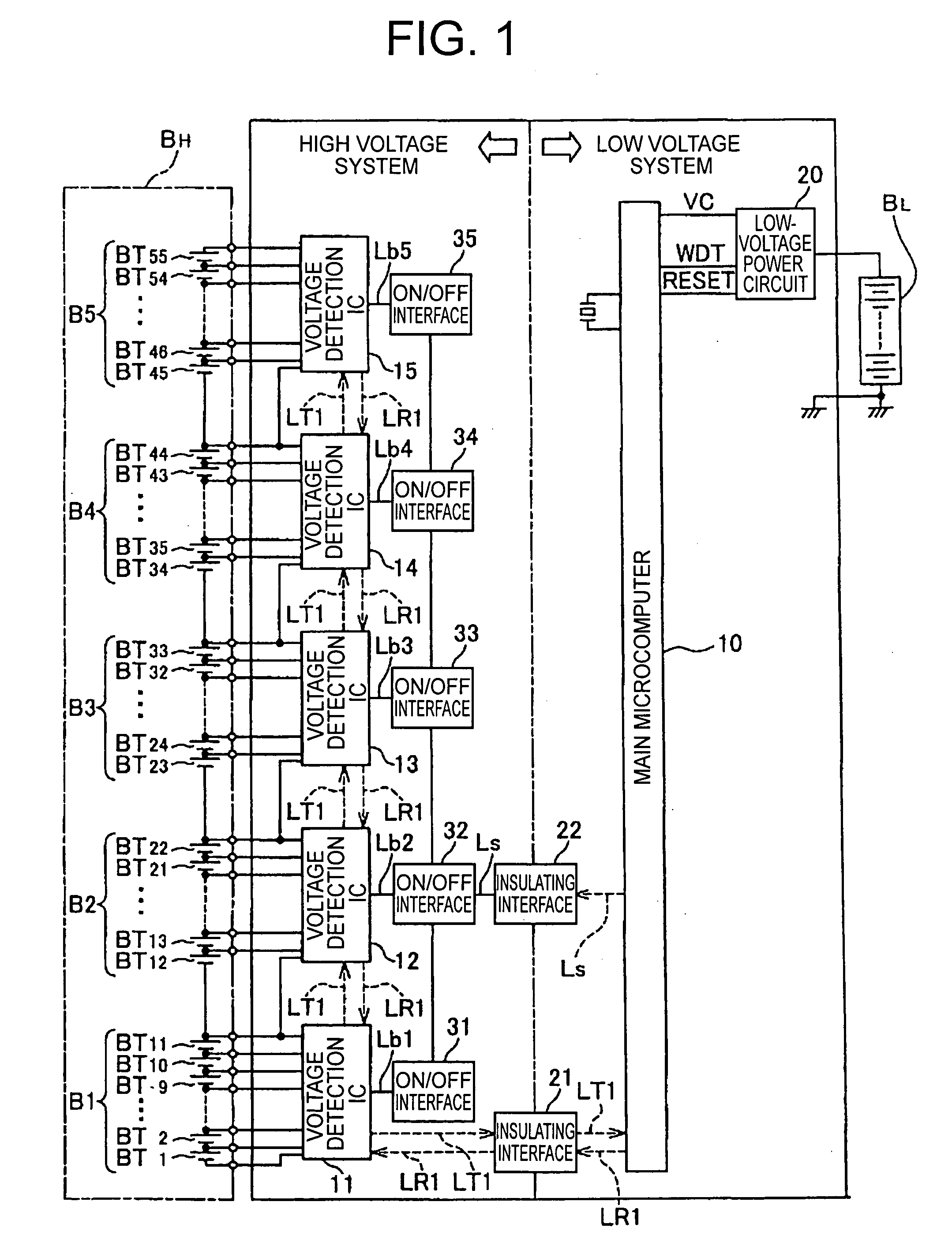
[0031]Embodiments of the present invention are explained by referring to drawings. In the preferred embodiment, a voltage detecting device is mounted on a vehicle. A reference numeral BL denotes a low-voltage battery. The low-voltage battery BL has a plurality of a secondary battery as shown in FIG. 1 The low-voltage battery BL powers a starter to start an engine and is connected with an alternator (not shown) as a battery changer.

[0032]A reference numeral BH in FIG. 1 denotes a high-voltage battery as a battery pack. The high-voltage battery BH powers an electric motor of a Hybrid Electric Vehicle (HEV) and is as appropriate connected with the alternator (not shown) as the battery charger.

[0033]The high-voltage battery BH is, for example, divided into for example five blocks B1-B5. Each block B1-B5 has eleven unit cells of BT1-BT11, BT12-BT22, BT23-BT33, BT34-BT44, and BT45-BT55. Each unit cell BT1-BT55 has a secondary battery.

[0034]The voltage detecting device has a main microcomp...


PUM


Abstract

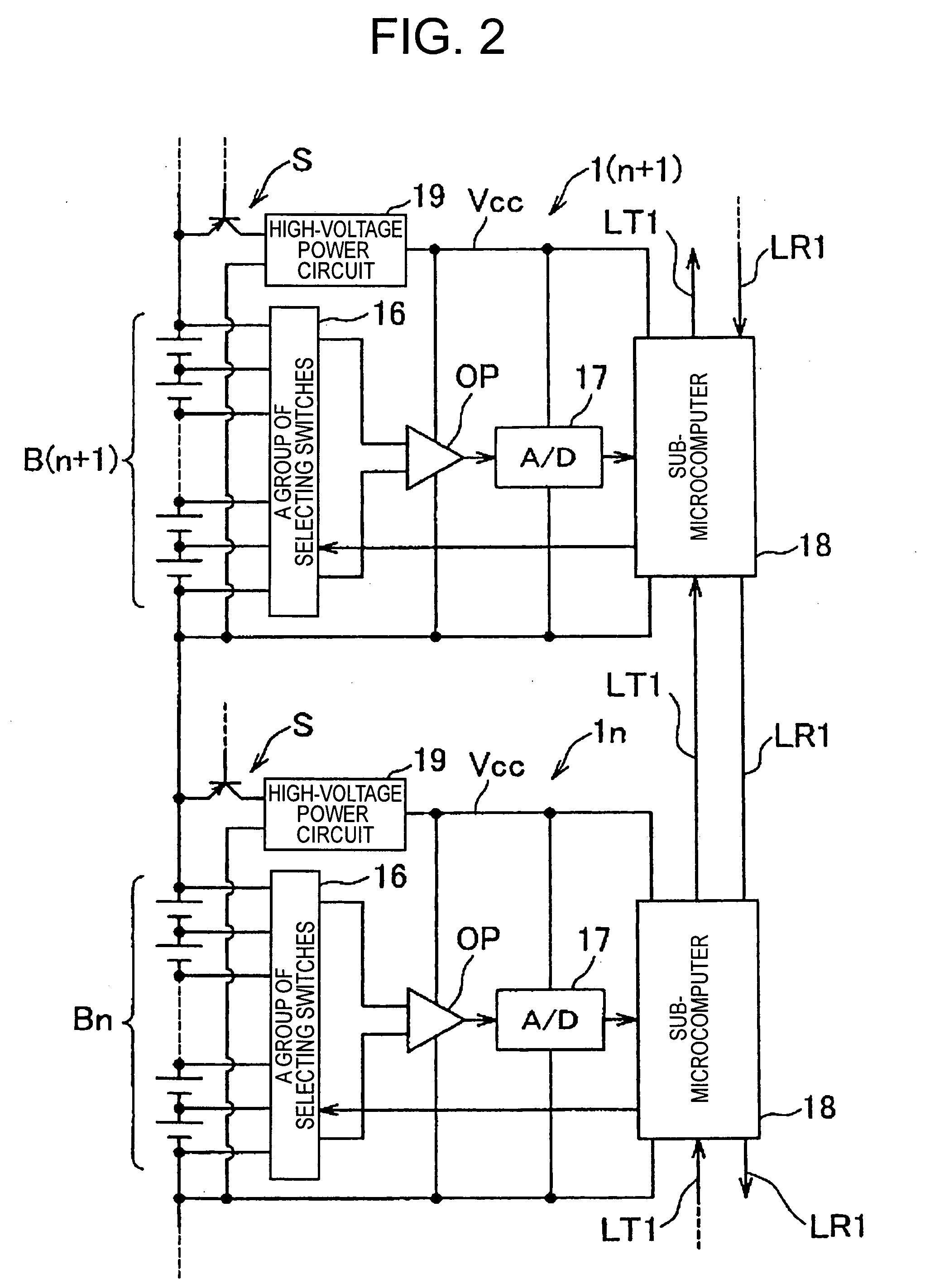
The present invention is to provide inexpensively a voltage detecting device for setting an address of each voltage detection IC even if a power source level of each voltage detection IC differs. A first transmitting line LT1 and a first receiving line LR1 connect a plurality of voltage detection ICs in series each other, and connect between the bottom voltage detection IC and the main microcomputer. The main microcomputer transmits an address number 0 to the bottom voltage detection IC. When the respective voltage detection ICs receive an address number through the first receiving line of a lower side from the main microcomputer, an address number adding 1 to the received address number is set as a self-address number. Furthermore, the respective voltage detection ICs transmit the address number which adds 1 to the received address number to the first transmitting line LT1 of an upper side.

Description

[0001]The priority application Number Japan Patent Application No. 2007-332683 upon which this patent application is based is hereby incorporated by reference.BACKGROUND OF THE INVENTION[0002]1. Filed of the Invention[0003]The present invention relates to a voltage detecting device, particularly to a voltage detecting device for detecting each voltage of each block of a plurality of blocks divided from a battery unit formed with a plurality of unit cells, which is secondary battery type, connected in series to each other.[0004]2. Description of the Related Art[0005]Recently, a hybrid electric vehicle (HEV), which travels by using both an engine and an electric motor, has been widely used. The HEV has a low voltage battery of 12 volts for starting the engine, and a high voltage battery for driving the electric motor. The high voltage battery is formed with a plurality of unit-cells, connected in series, such as a nickel-metal hydride secondary battery or a lithium secondary battery.[...

Claims


Application Information

Patent Timeline
IPC IPC(8): G01R31/36
CPCG01R31/3658G01R31/362G01R31/3835G01R31/396
Inventor ISHIKAWA, SATOSHIMATSUURA, KIMIHIROSEKIZAKI, MASASHI
Owner YAZAKI CORP
Learn More