Air Conditioner

a technology of air conditioner and heat exchanger, which is applied in the direction of railway heating/cooling, vehicle heating/cooling devices, vehicle components, etc., can solve the problems of lack of heating, insufficient heat exchanger, and inability to heat air with heat exchangers, so as to suppress the flow resistance of warm air passing through the warm air path, the effect of fast air speed and large volum

Inactive Publication Date: 2009-07-02
CALSONIC KANSEI CORP
View PDF8 Cites 7 Cited by
  • Summary
  • Abstract
  • Description
  • Claims
  • Application Information

AI Technical Summary

Benefits of technology

[0010]In order to achieve the foregoing object, according to the present invention, there is provided an air conditioner that includes: on a downstream side of a cooling condenser, a mixing chamber to which a warm air path having a heating heat exchanger and a bypass path bypassing the warm air path are connected and in which downstream sides of the warm air path and the bypass path merge together to mix flows of air coming therethrough; and a blowout path connected to the mixing chamber. At a position where air speed of warm air having passed the heat exchanger is fast, an auxiliary heater is disposed in series with the heat exchanger so that a portion of the warm air passes through the auxiliary heater, and another portion of the warm air bypasses the auxiliary heater by passing through an area where the air speed of the warm air having passed the heat exchanger is slow.
[0011]According to the present invention having this constitution, when the warm air path is opened at heating, a portion of the warm air having passed the heat exchanger passes through the auxiliary heater at a fast air speed and hence in a large volume, so that auxiliary heating can be made sufficiently by the auxiliary heater. Furthermore, another portion of the warm air bypasses the auxiliary heater by passing through the area where the air speed is slow. Therefore, the flow resistance of the warm air passing through the warm air path can be suppressed, thereby securing a sufficient volume of the warm air. Accordingly, by heating further the warm air having passed through the heat exchanger by the auxiliary heater and then mixing the heated air with the warm air having bypassed the auxiliary heater, a comparatively high temperature and large volume of warm air can be blown even when the heating heat exchanger cannot generate sufficient heat.
[0012]According to the present invention, even when the heating heat exchanger cannot generate sufficient heat at the time of heating, a comparatively high temperature and large volume of warm air can be blown out. Therefore, an air conditioner can be obtained which provides sufficient heating even, for example, when an engine is not warmed up immediately after the start of a vehicle.

Problems solved by technology

Immediately after start of the vehicle, however, the engine is not warm and therefore the coolant temperature is low, so that the air cannot be heated with the heat exchanger.
Particularly in a cold district, the heat exchanger is not enough to heat the air because outside temperature is extremely low.
Accordingly, a small volume of the warm air passing through the auxiliary heater 103 is heated further by the same and then blown out to a vehicle cabin after mixed with the warm air that has bypassed the auxiliary heater 103, which disadvantageously leads to a lack of heating because of a comparatively low temperature of this blown-out warm air.
Accordingly, when the warm air is heated further by the auxiliary heater 113 and then blown out to the vehicle cabin, this small volume of the blown-out warm air disadvantageously leads to a lack of heating.

Method used


Image

  • Air Conditioner
  • Air Conditioner
  • Air Conditioner

Examples


Embodiment Construction

[0019]An air conditioner according to an embodiment of the present invention will be described below with reference to the drawings.

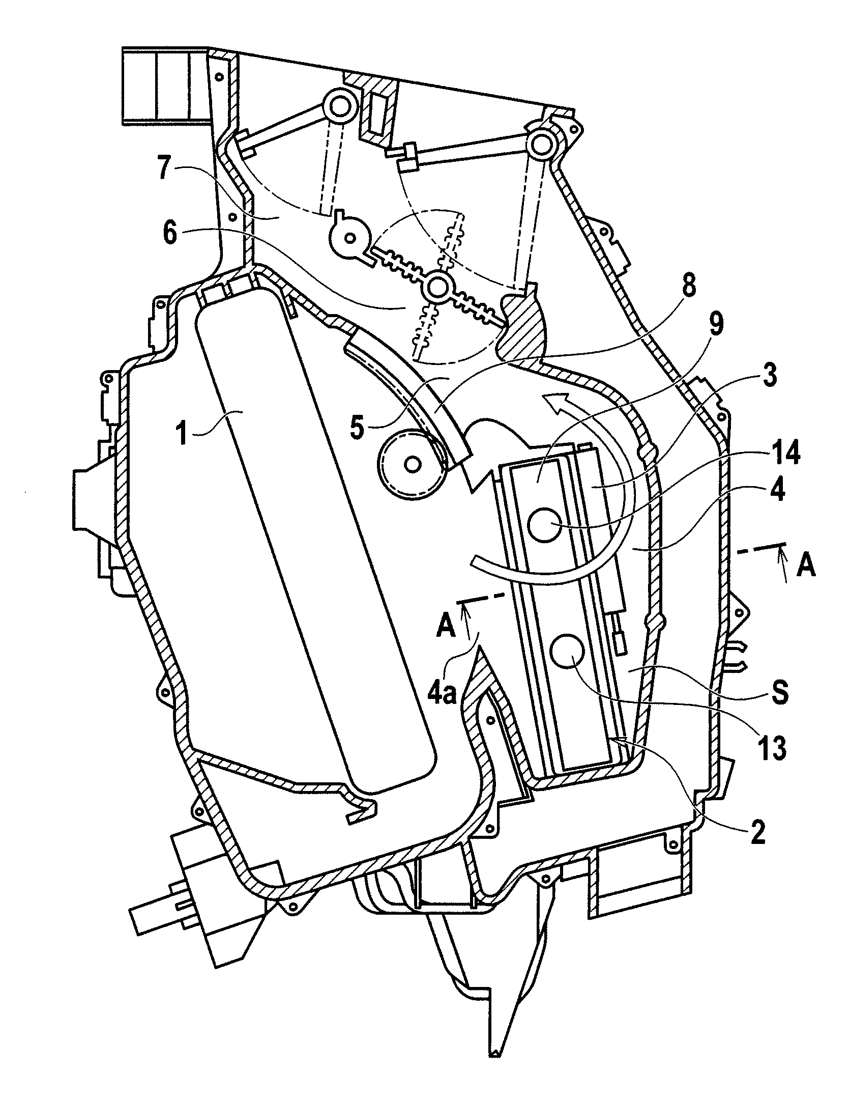
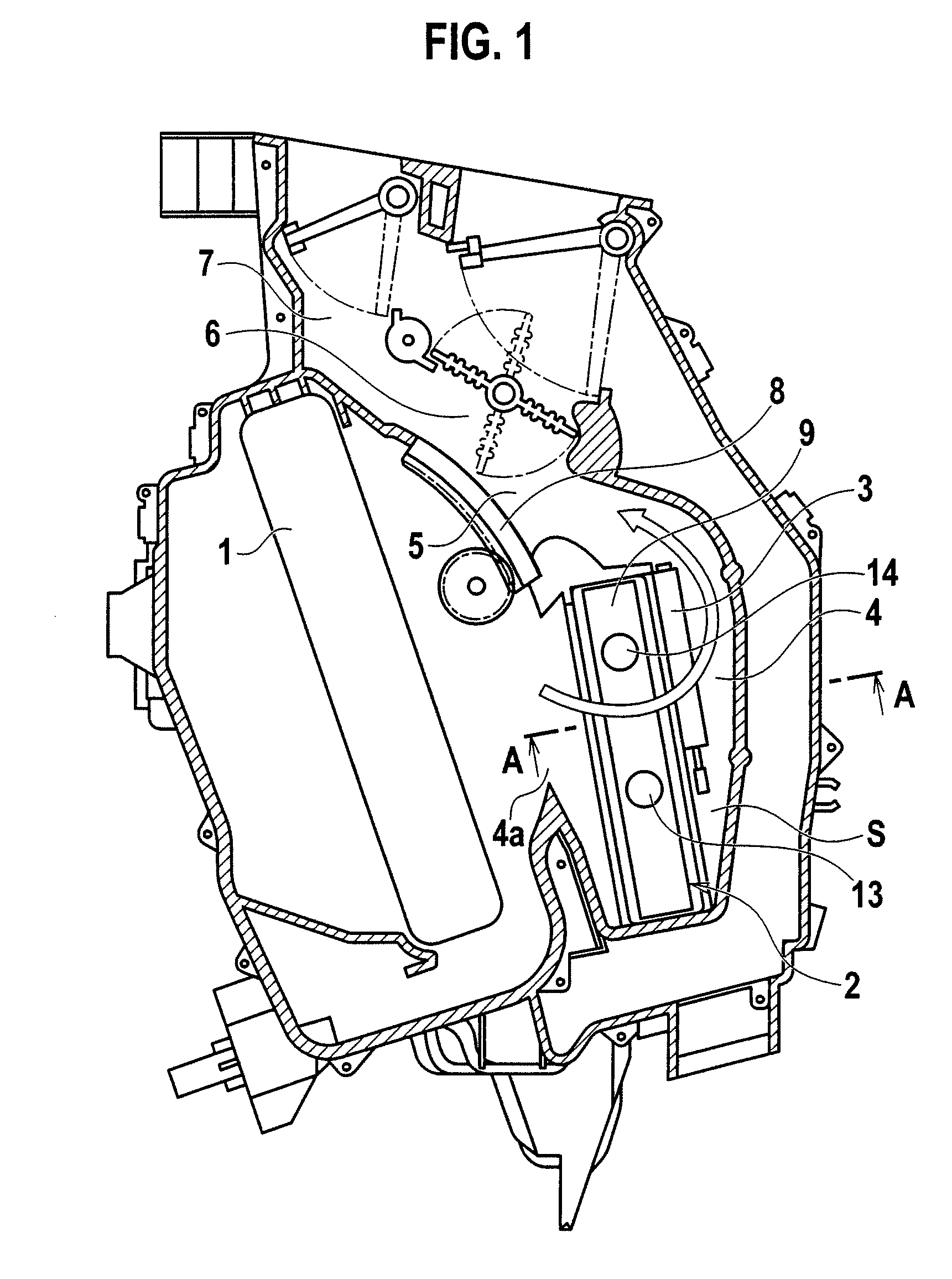
[0020]FIG. 1 is a cross section of the air conditioner according to the embodiment of the present invention, FIG. 2 is a cross section along a line A-A of FIG. 1, FIG. 3 is a front view of a heating heat exchanger provided in the embodiment, and FIG. 4 is a front view of a modified example of the heat exchanger provided in the embodiment.

[0021]Referring to FIGS. 1 and 2, the air conditioner in this embodiment includes: on a downstream side of a cooling condenser (evaporator) 1, a mixing chamber 6 to which a warm air path 4 having a heating heat exchanger 2 and an auxiliary heater 3 as well as a bypass path 5 bypassing the warm air path 4 are connected and in which downstream sides of both the warm air path 4 and the bypass path 5 merge together to mix flows of air coming therethrough; a blowout path 7 connected to the mixing chamber 6; and an air mix do...


PUM


Abstract

An air conditioner includes, on a downstream side of a condenser 1, a mixing chamber to which a warm air path 4 and a bypass path 5 are connected and in which downstream sides of the warm air path 4 and the bypass path 5 merge together to mix flows of air coming therethrough, and a blowout path 7 connected to the mixing chamber 6. At a position where air speed of warm air having passed through a heat exchanger 2 is fast, an auxiliary heater 3 is provided through which a portion of the warm air passes, and is disposed in series with the heat exchanger 2. Another portion of the warm air passes through an area where the air speed of the warm air is slow thereby to bypass the auxiliary heater 3. Therefore, auxiliary heating can be made sufficiently by the auxiliary heater 3. Furthermore, another portion of the warm air passes through the area where the air speed is slow thereby to bypass the auxiliary heater 3, which suppresses a flow resistance of the warm air passing through the warm air path 4, thereby securing the volume of the warm air.

Description

TECHNICAL FIELD[0001]The present invention relates to an air conditioner in which an electrically controlled auxiliary heater is provided on a downstream side of a heat exchanger for heating air (heater core).BACKGROUND ART[0002]An air conditioner for vehicles generally has a heating heat exchanger (heater core) that heats air by utilizing hot water from a vehicle's engine (engine coolant), and heats a cabin of the vehicle by heating air taken from inside and outside the vehicle with this heat exchanger and then blowing the heated air to the vehicle cabin. Immediately after start of the vehicle, however, the engine is not warm and therefore the coolant temperature is low, so that the air cannot be heated with the heat exchanger. Particularly in a cold district, the heat exchanger is not enough to heat the air because outside temperature is extremely low. Therefore, there has been provided an auxiliary heater that is composed of an electric heater and the like for applying auxiliary ...

Claims


Application Information

Patent Timeline
Patent Type & Authority Applications(United States)
IPC IPC(8): B60H3/00
CPCB60H2001/00128B60H1/00028
Inventor KOMABA, AKIHIRO
Owner CALSONIC KANSEI CORP
Why Eureka
Try Eureka