Geothermal heat exchange system and method

a geothermal heat exchange and heat depot technology, applied in geothermal energy generation, geothermal collectors, refrigerating machines, etc., can solve the problems of defective loops, inapplicability of horizontal loops for a small yard, and require a modest size of land, so as to achieve sufficient heat transfer

Inactive Publication Date: 2009-07-02
NOBLE GEOFURNACE
View PDF13 Cites 26 Cited by
  • Summary
  • Abstract
  • Description
  • Claims
  • Application Information

AI Technical Summary

Problems solved by technology

Thus, due to the limitations of the circulating pump or compressor capacity, both types of systems are of limited length and diameter geothermal loop tube for conducting the heat exchange.
Thus, use of horizontal looping for a house or building with a small yard is not practical.
And these systems also still generally require a modest size of land to install the necessary equipment.
Unevenness of the geothermal contact or uneven geothermal heat transfer due to differences in underground soil composition, variation and contact results in a defective loop.
In such a defective loop, the refrigerant or water passes underground, then through defective lines, resulting in low temperature change leading to dysfunction.
In case of the direct heat exchange systems, the defective line has the lowest pressure load during the heating mode due to inability to vaporize refrigerant, and the highest pressure during the cooling mode due to lesser liquefying of the refrigerant, resulting in concentrated movement of the refrigerant through lower pressure lines due to the dysfunction.
In case of the water source model, the propylene glycol, antifreeze used for heating mode use has high viscosity in lower temperature, leading to the restricted movement of the liquid movement through the defective lines.
Thus, unequal flow of water or refrigerant flow results between the dysfunctional and well functioning lines due to the high viscosity or comparative lower pressure of the line, which sometimes leads to the failure of the whole system.
Another problem with existing geothermal heat exchange systems is that the prolonged running time of the geothermal heat pumps often causes super freezing of the land during the heating mode and super heating of the land during the cooling mode, reducing the efficiency of the heat pump system.
Therefore, both types of existing systems require high cost installation due to extensive drilling, land excavation and labor requirement, as well as requiring a relatively long period of time to install.

Method used


Image

  • Geothermal heat exchange system and method
  • Geothermal heat exchange system and method
  • Geothermal heat exchange system and method

Examples


Embodiment Construction

[0048]In the following description, for purposes of explanation, specific numbers, materials and configurations are set forth in order to provide a thorough understanding of the invention. It will be apparent, however, to one having ordinary skill in the art, that the invention may be practiced without these specific details. In some instances, well-known features may be omitted or simplified so as not to obscure the present invention. Furthermore, reference in the specification to “one embodiment” or “an embodiment” means that a particular feature, structure or characteristic described in connection with the embodiment is included in at least one embodiment of the invention. The appearances of the phrase “in an embodiment” in various places in the specification are not necessarily all referring to the same embodiment.

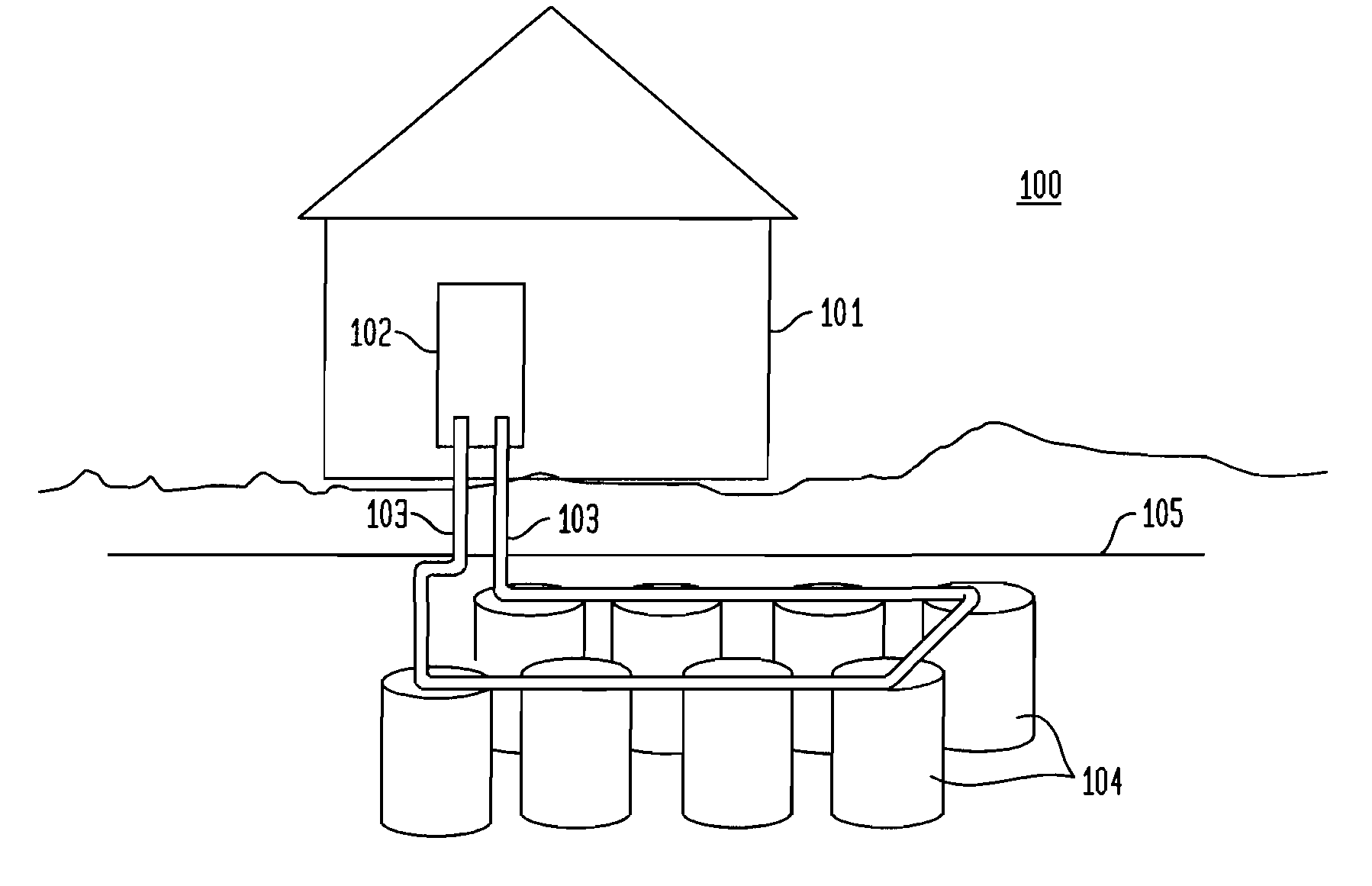
[0049]The present invention advantageously provides for geothermal heat exchange system and method that does not require high cost installation due to extensive drilli...


PUM


Abstract

Provided is a geothermal heat exchange system and method including a plurality of heat depots, each including a sealed container filled with a heat exchange fluid and further including an input heat transfer line and an output heat transfer line for carrying the heat transfer fluid. The input line proceeds through a top surface of the container at least a minimal distance into the container, and the output heat transfer line originates immediately at the upper surface of the container. Multiple heat depots connected to one another in a continuous unbroken chain are also provided.

Description

CROSS-REFERENCE TO RELATED APPLICATIONS[0001]This application claims the benefit of U.S. Provisional Patent Application Ser. No. 61 / 017,907, filed Dec. 31, 2007, and U.S. Provisional Patent Application Ser. No. 61 / 026,734, filed Feb. 7, 2008, the entire disclosures of which are hereby incorporated by reference.FIELD OF THE INVENTION[0002]This invention generally relates to a system and method for geothermal heat exchange method utilizing heat depots, and, more particularly, to geothermal heat exchange utilizing heat depots having improved efficacy of heat exchange while greatly reducing required area of installation and removing the need for extensive drilling.BACKGROUND OF THE INVENTION[0003]Geothermal heat exchange systems have been in use for some time. In a typical geothermal heat exchange systems, a working fluid, such as water, is used to carry heat between an internal heat exchanger in the user's location and a geothermal mass. Heat exchange systems often are designed to have...

Claims


Application Information

Patent Timeline
Patent Type & Authority Applications(United States)
IPC IPC(8): F24J3/08
CPCY02E10/16F24J3/086F24T10/30Y02E10/10F25B30/06F28D15/00
Inventor SONG, SAEHEUM
Owner NOBLE GEOFURNACE
Why Eureka
Try Eureka