Porous honeycomb water treatment device

a honeycomb and treatment device technology, applied in the direction of evaporator regulation/control, fractional distillation, separation processes, etc., can solve the problems of large amount of wasted heat, and large amount of fume produced

Inactive Publication Date: 2009-07-02
SUN GARY
View PDF3 Cites 16 Cited by
  • Summary
  • Abstract
  • Description
  • Claims
  • Application Information

AI Technical Summary

Benefits of technology

[0005]A porous honeycomb water treatment device can be realized by two embodiments. A first embodiment of the porous honeycomb water treatment device comprising a fractionator (1) is a hollow, vacuum, and high pressure distillation column, where salt water alternatively heated up to 100° C. or cooled down to 0˜18° C.; a bottom product exit (13) formed at a bottom of the fractionator (1); an inlet pipe (11) disposed above the fractionator (1) injects salt water in the fractionator (1); a top product outlet pipe (12) disposed above the fractionator (1) discharges water vapor out of the fractionator (1); and, at least, one tray (4) disposed inside the fractionator (1) equidistantly arranged in neat stack; the tray (4) is composed of a plurality of heat pipe (40) filled with working fluid mixed with nano-scale metallic particulates; the heat pipes (40) are arrayed in parallel to one another and equidistantly supported on a hollowed-out frame (41) at an inclin

Problems solved by technology

Though water resource developing plan are never stop running, efforts to furnish fresh water suitable for human consumption and irrigation made renowned great rivers around the world are replete with water power and dam construction, but gradual resource shortage problem still is floated to the top of water for decades.
Though distillation m

Method used


Image

  • Porous honeycomb water treatment device
  • Porous honeycomb water treatment device
  • Porous honeycomb water treatment device

Examples


first embodiment

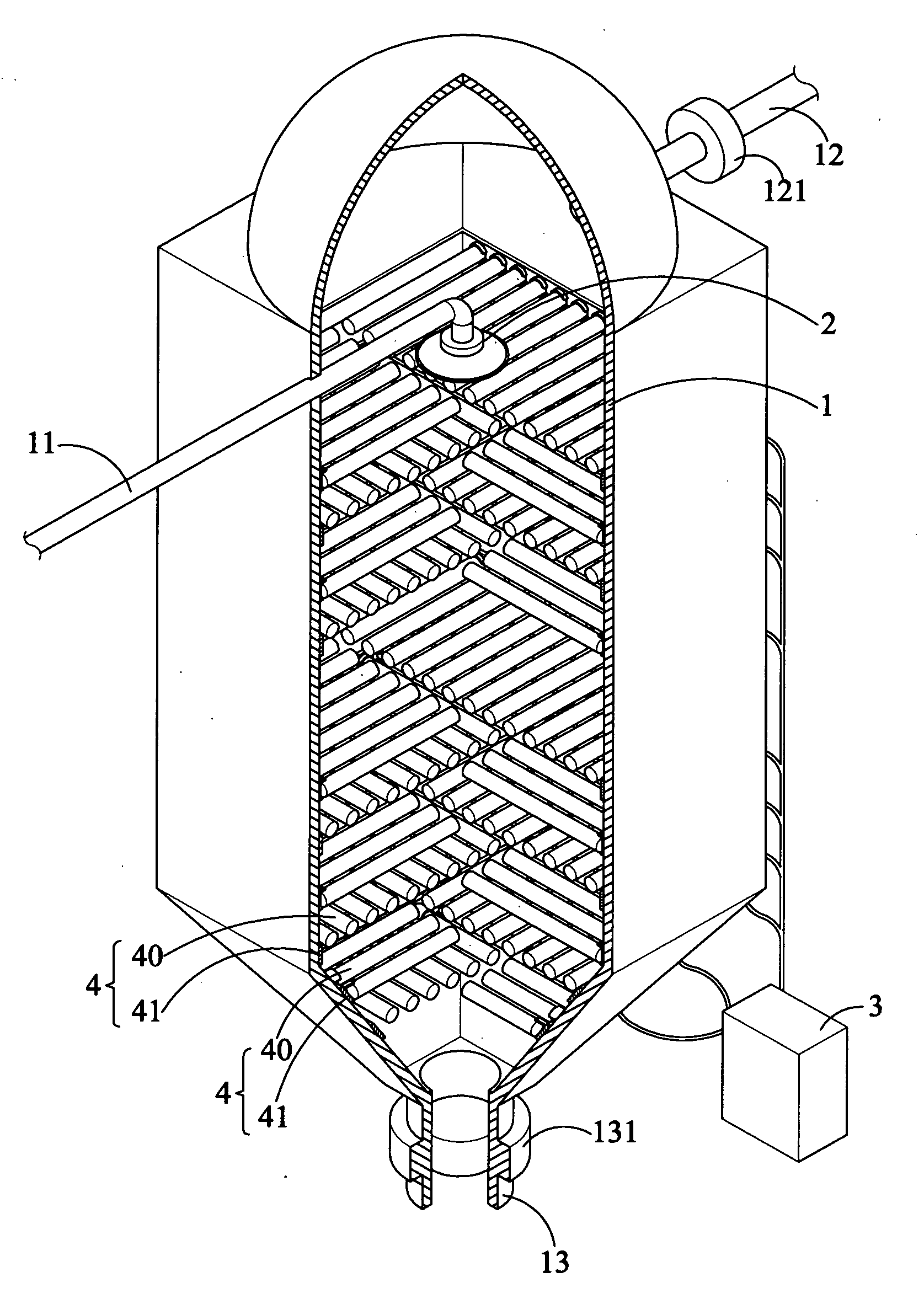
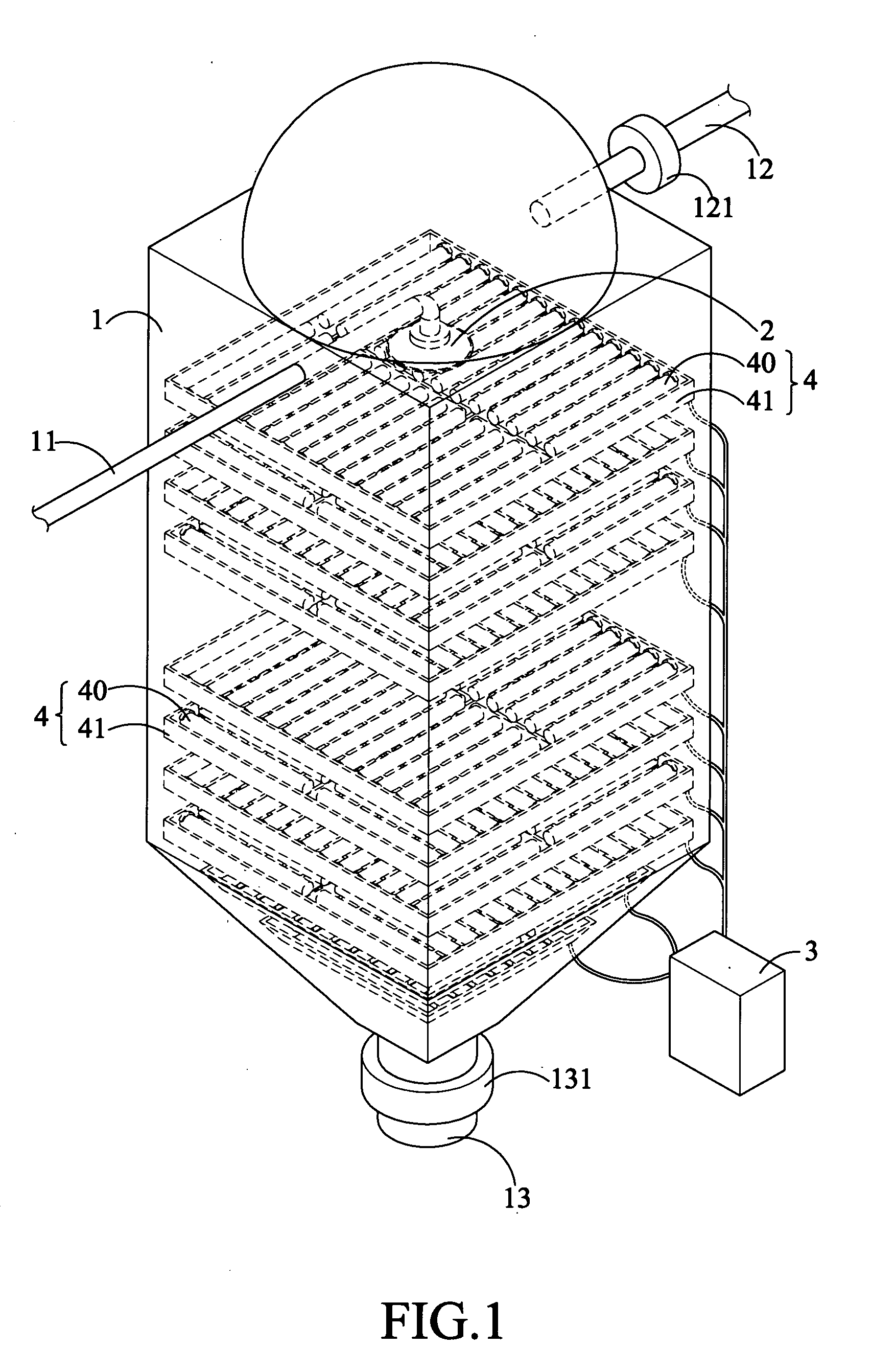
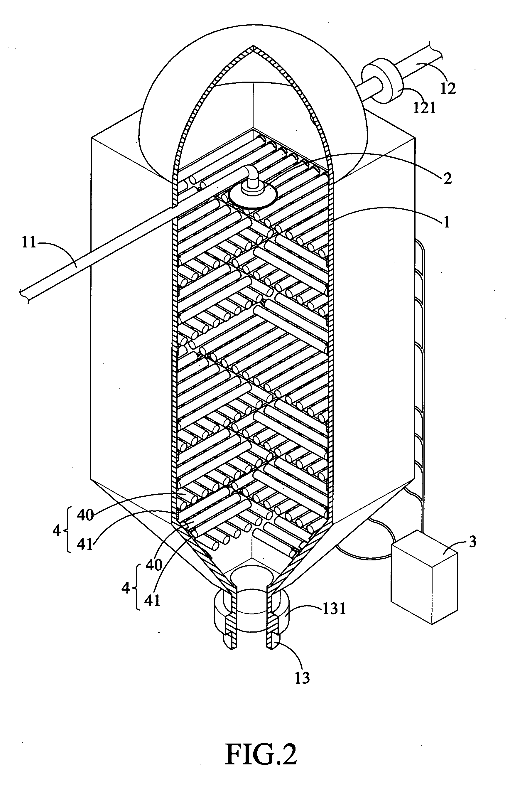
[0018]As shown in FIGS. 1˜3C, a porous honeycomb water treatment device includes a fractionator (1) allows salt water exposed to high pressure and vacuum condition; a bottom product exit (13) formed at a bottom of the fractionator (1); an inlet pipe (11) disposed above the frationator (1) injects salt water into the fractionator (1); a top product outlet pipe (12) disposed above the fractionator (1) discharges water vapor out thereof; at least, one tray (4) disposed inside the fractionator (1), when more than two trays (4) vertical aligned in a neat stack with equidistant gap kept between each two neighbored trays; each of which having a plurality of heat pipes (40) arrayed in parallel to one another and equidistantly supported on a hollowed-out frame (41).

[0019]Take advantage of heat pipes (40) can be heated instantly inside the fractionator (1); which is operated under high pressure gets, at least, a low to medium vacuum. Therefore, a boiling point of salt water can be lowered. In...

second embodiment

[0030]As shown in FIGS. 6 and 7, a porous honeycomb water treatment device comprising a hollow, vacuum, and high pressure fractionator (1), a bottom product exit (13) formed at a bottom of the fractionator (1), at least, one inlet pipe (11) centrally disposed above the fractionator (1) injects salt water in the fractionator (1), a top product outlet pipe (12) disposed above the fractionator (1) discharges water vapor out of the fractionator (1), at least, one set of trays (4) fit through the fractionator (1) are equidistantly vertical aligned in a neat stack inside the fractionator (1), each of the trays (4) is composed of a plurality of heat pipes (40) arrayed in parallel to one another and equidistantly supported on a hollowed-out frame (41) at an inclined angle (θ); at least, each of the tray (4) is clad with a condenser (43) at a higher end to wrap up higher ends of the heat pipes (40); at least, each of the tray (4) clad with a heating device (42) at a lower end to wrap up lowe...


PUM


Abstract

A porous honeycomb water treatment device washes out deposited salt automatically with high heat exchange rate to produce sufficient fresh water, a hollow, vacuum, and high pressure distillation column, where salt water alternatively heated up to 100° C. or cooled down to 0˜18° C.; a bottom product exit (13) formed at a bottom of the fractionator (1); an inlet pipe (11) disposed above the fractionator (1) injects salt water in the fractionator (1); a top product outlet pipe (12) disposed above the fractionator (1) discharges water vapor out of the fractionator (1); and at least, one tray (4) disposed inside the fractionator (1) equidistantly arranged in neat stack; the tray (4) is composed of a plurality of heat pipe (40) filled with working fluid mixed with nano-scale metallic particulates; the heat pipes (40) are arrayed in parallel and equidistantly supported on a hollowed-out frame (41) at an inclined angle (θ).

Description

FIELD OF THE INVENTION[0001]The present invention is related to a porous honeycomb water treatment device.DESCRIPTION OF PRIOR ARTS[0002]Although 70% of the mother earth surface is filled with water, but not all freshwater. Though water resource developing plan are never stop running, efforts to furnish fresh water suitable for human consumption and irrigation made renowned great rivers around the world are replete with water power and dam construction, but gradual resource shortage problem still is floated to the top of water for decades. Fresh water obtained through several kinds of water desalination treatments such as distillation, Aero-Evapo-condensation-Process (AECP), reverse osmosis, electrolysis, and ion exchange.[0003]Distillation and reverse osmosis are recognized as two of good ways to provide better fresh water. Though distillation may produce large amount of fresh water with inexpensive, durable boilers, but energy consumption and environmental impact are more serious ...

Claims


Application Information

Patent Timeline
IPC IPC(8): B01D3/14
CPCB01D1/0041B01D1/0082B01D3/42B01D3/26B01D1/16
Inventor SUN, GARY
Owner SUN GARY
Why Eureka
Try Eureka