Personal Safety System

a safety system and personal technology, applied in life-saving, waterborne vessels, instruments, etc., can solve the problem that the crew may be off the vessel for a relatively long time, and achieve the effect of reducing the incidence of false alarms

Inactive Publication Date: 2009-07-02
ROYAL NAT LIFEBOAT INSTITUTION
View PDF9 Cites 35 Cited by
  • Summary
  • Abstract
  • Description
  • Claims
  • Application Information

AI Technical Summary

Benefits of technology

[0012]Accordingly, the personal safety device and base unit are provided which are coupled over a local communications link. Periodic messages are transmitted between the personal safety device and the base unit. Should it be recognised that messages are no longer being transmitted between the personal safety device and the base unit, an alarm mechanism is activated both at the personal safety device and at the base unit. In this way, the member of crew wearing the personal safety device will detect the alarm mechanism activating and be provided with the assurance that a similar alarm mechanism is activating on the base unit.
[0038]Hence, when the charge in the battery becomes less than a predetermined amount, one or more personal safety device deactivating messages are transmitted to the base unit to indicate to the base unit that the personal safety device will be deactivating and the personal safety device will thereafter deactivate. In this way, it will be appreciated that the occurrence of false alarms due to low battery levels causing erroneous transmissions will be reduced.

Problems solved by technology

Also, because the emergency signal is only detected by a transiting satellite, the member of the crew may be off the vessel for a relatively long period of time prior to the emergency signal even being detected.

Method used


Image

  • Personal Safety System
  • Personal Safety System
  • Personal Safety System

Examples


Embodiment Construction

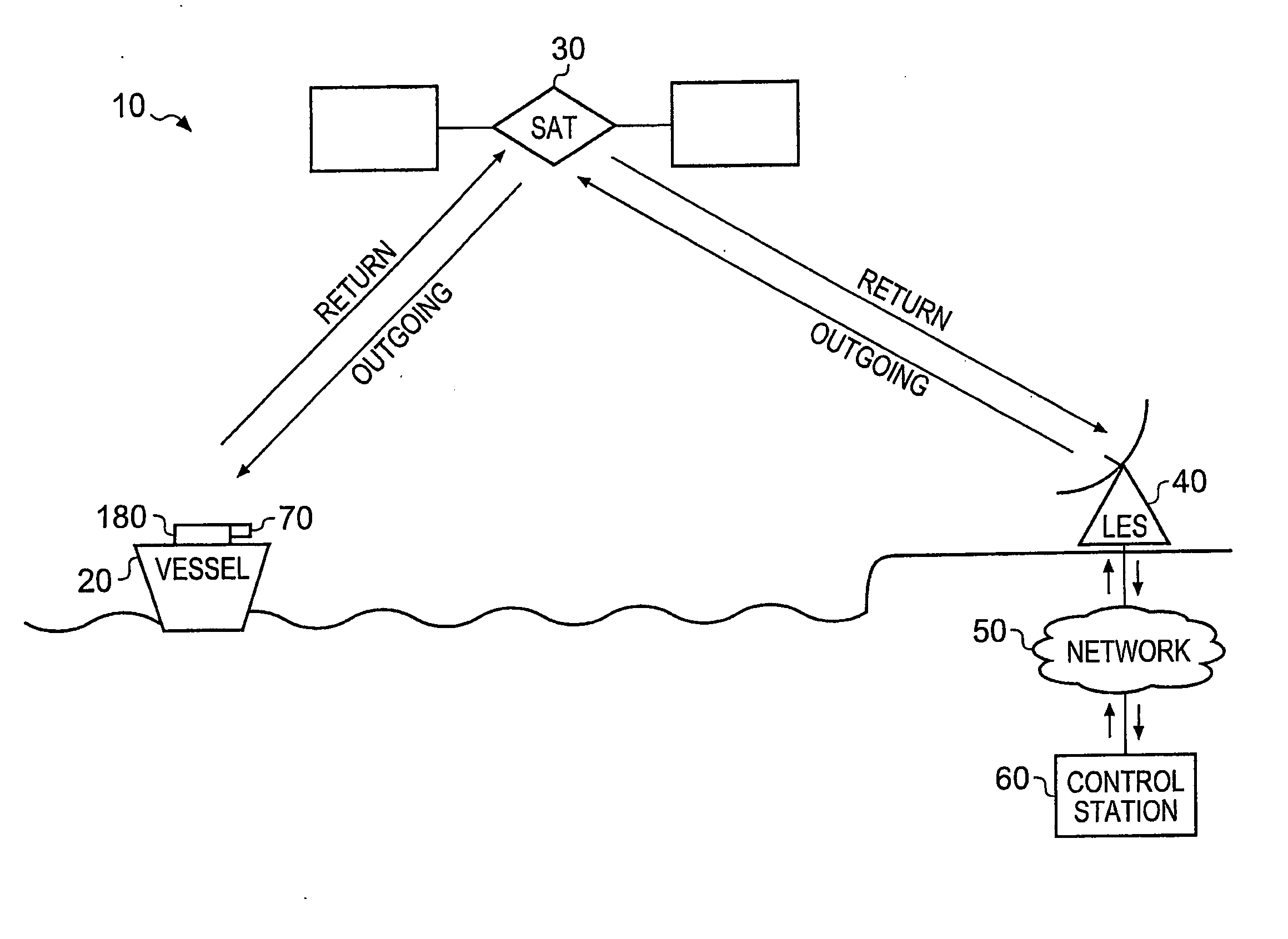
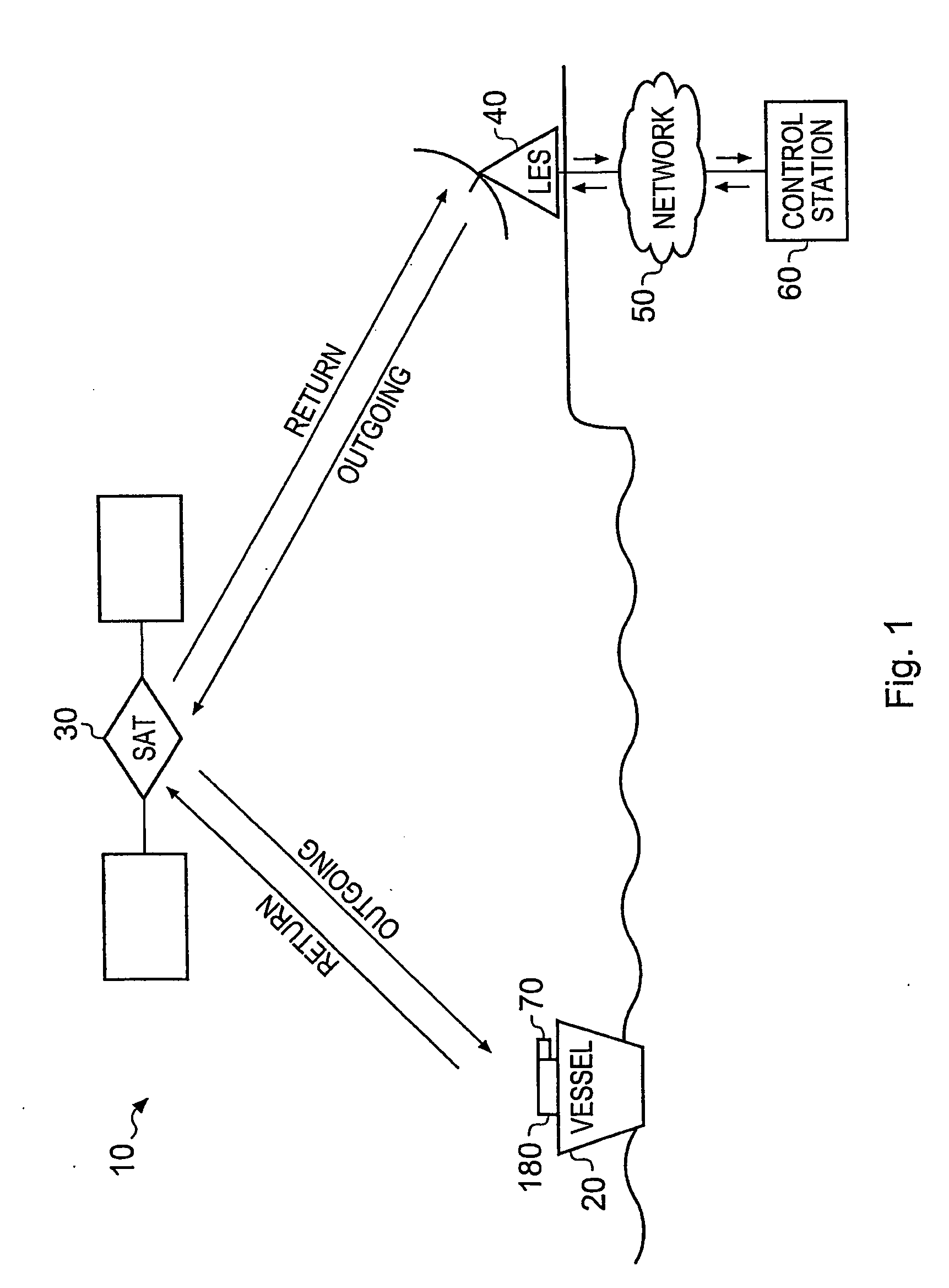
[0067]FIG. 1 illustrates a communication system according to an embodiment of the present invention. The communication system links a vessel 20 via a satellite 30 with a land earth station 40 using a communication link. The land earth station 40 is coupled via a network (for example, the internet) with a control station 60. Messages are transmitted over the communications link to provide an indication to the control station 60 of whether or not the vessel 20 is likely to be in an emergency situation.

[0068]In this example, the communication link is provided by the Inmarsat (trademark) D+ satellite network, which provides a low cost time division multiplexed bearer for transmission of data at a low bit rate. However, it will be appreciated that any suitable satellite (such as Iridium (trademark)) or other communications link (such as GSM) having an appropriate antenna arrangement could be utilised.

[0069]The Inmarsat (trademark) D+ satellite network provides a relatively high power out...


PUM


Abstract

A personal safety system is disclosed. The personal safety system comprises: a personal safety device and a base unit coupled over a local communications link; transceiver logic operable to transmit a periodic status message and an acknowledgement message generated in response to each received status message between said personal safety device and said base unit over said local communications link; and alert logic operable, in the event that said transceiver logic indicates that a number of either of said status and acknowledgement messages fail to be transmitted between said personal safety device and said base unit, to activate an alarm mechanism on both said personal safety device and said base unit. Accordingly, the member of crew wearing the personal safety device will detect the alarm mechanism activating and be provided with the assurance that a similar alarm mechanism is activating on the base unit.

Description

FIELD OF THE INVENTION[0001]The present invention relates to a personal safety system.BACKGROUND OF THE INVENTION[0002]Personal safety systems are known. In one type of known safety system, such as those used with vessels, a water or manually-activated individual safety beacon is typically worn by crew of the vessel. In the event that the member of the crew gets into difficulty then the individual safety beacon may be activated. Similarly, should a member of the crew fall overboard, then a water-detection mechanism will detect the presence of water and activate the individual safety beacon.[0003]When the individual safety beacon activates, a low power transmission occurs on the maritime emergency channel (transmitted at 406), this low powered emergency transmission is subsequently detected by a satellite when transiting over the geographic region of the individual safety beacon and the position of the individual safety beacon can be determined using standard Doppler techniques. In a...

Claims


Application Information

Patent Timeline
Patent Type & Authority Applications(United States)
IPC IPC(8): G08B23/00G08B21/00B63C9/00
CPCB63C9/00G08B21/025G08B21/0233G08B21/0216B63C9/0005G08B21/02G08B21/22
Inventor CLARK, CECILMORGAN, MARK
Owner ROYAL NAT LIFEBOAT INSTITUTION
Why Eureka
Try Eureka