Supercharge Your Innovation With Domain-Expert AI Agents!

Image forming method and image forming apparatus

a technology of image forming and forming method, which is applied in the direction of printing, other printing apparatus, etc., can solve the problems of increasing the cost of increasing the resolution of the detecting section, the failure of the ink clogging, and the increase of the load of arithmetic calculating

Inactive Publication Date: 2009-07-02
KONICA MINOLTA INC
View PDF7 Cites 2 Cited by
  • Summary
  • Abstract
  • Description
  • Claims
  • Application Information

AI Technical Summary

Benefits of technology

[0007]To overcome the abovementioned drawbacks in conventional image forming method and apparatus, it is one of objects of the present invention to provide image forming method and apparatus, each of which makes it possible to conduct the countermeasure, for eliminating such a defect that the recording material is not outputted from the recording element, with an accuracy lower than the arranging resolution of the recording elements, when forming an image in such a manner that plural kinds of recording materials, belonging to a same color category but being different in density, are emitted and distributed onto / over a recording medium by a plurality of recording elements, respectively, so as to form dots representing the image to be printed on the recording medium.

Problems solved by technology

In the ink-jet printer or the like, an image is formed on a recording paper sheet (recording medium) by emitting ink droplets (recording materials) from a plurality of nozzles (included in the recording elements) In this case, an ink clogging failure is liable to occur, and accordingly, a white line is generated in the image to be formed on the recording paper sheet, due to an influence of a nozzle suffered by this ink clogging failure (a defective nozzle).
To cope with such the shortcoming, there have been arisen various kinds of problems, such as a cost increase for increasing the resolution of the detecting section, an increase of arithmetic calculating load, etc.

Method used


Image

  • Image forming method and image forming apparatus
  • Image forming method and image forming apparatus
  • Image forming method and image forming apparatus

Examples


first embodiment

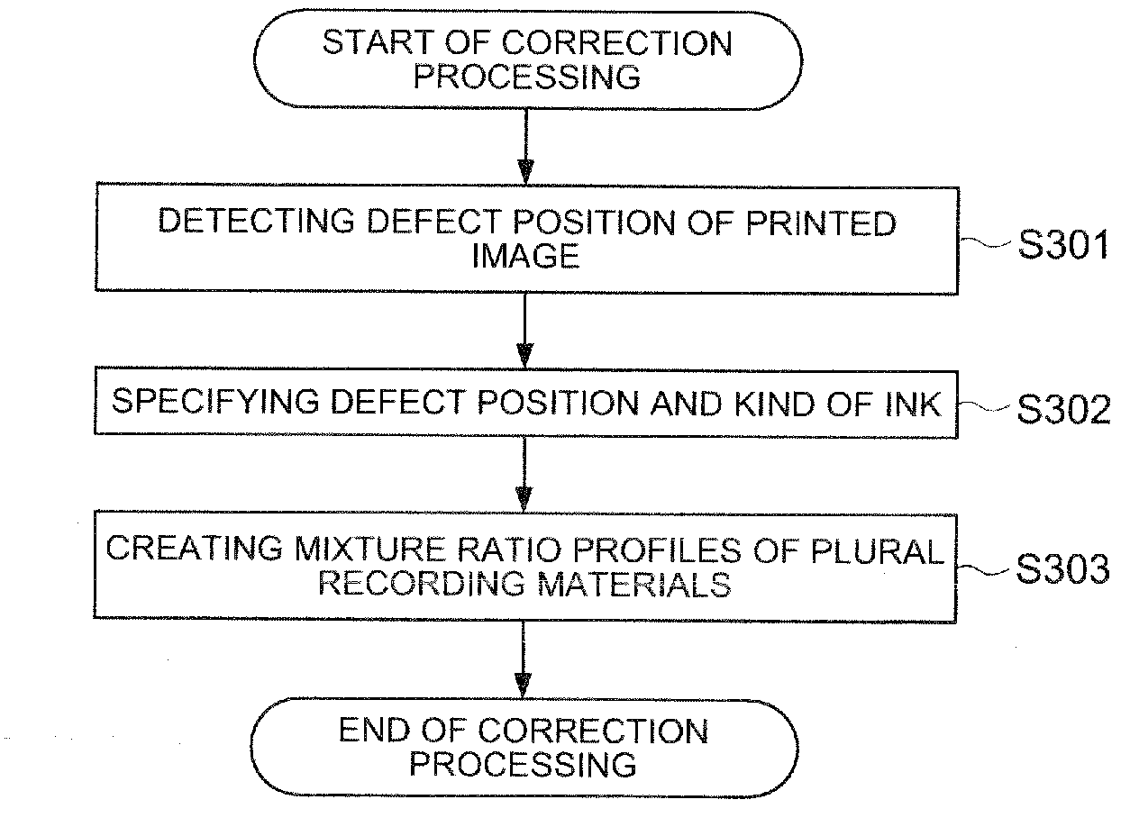
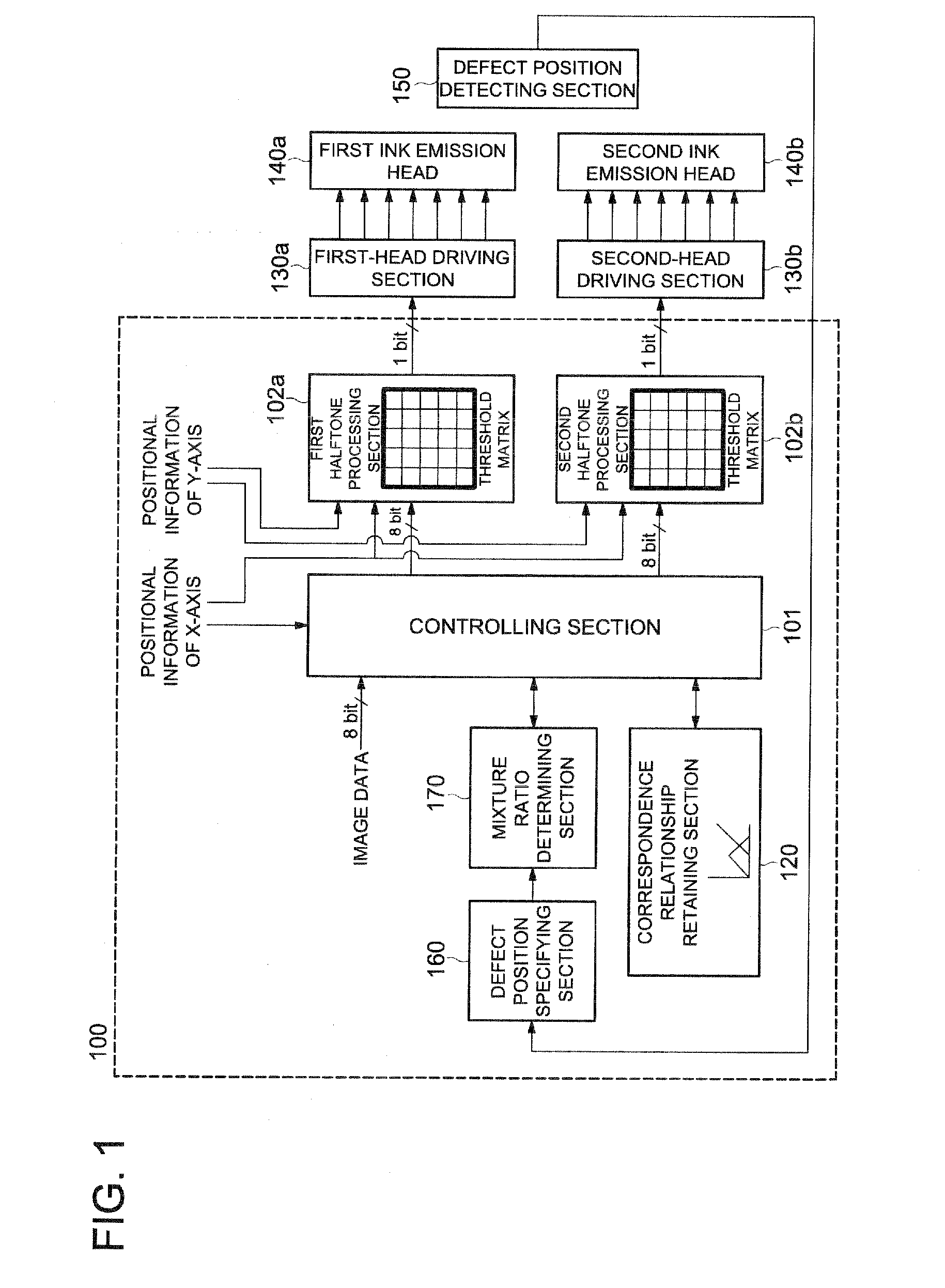
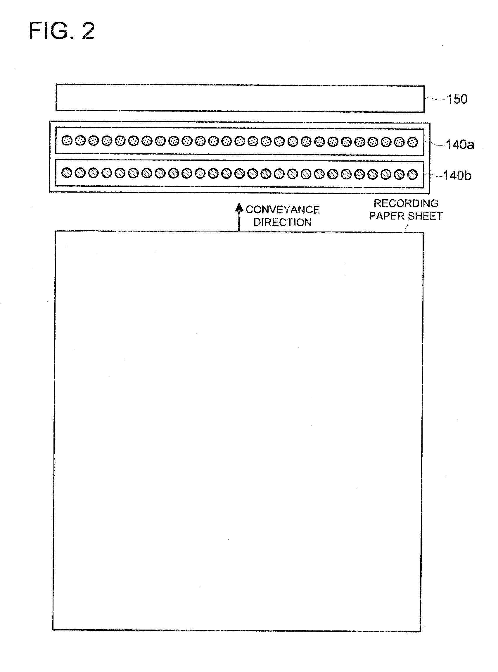
[0046]Referring to the drawings, the first embodiment of the present invention will be detailed in the following. Initially, the image forming method and apparatus, embodied in the present invention, will be detailed in the following.

[0047]In this connection, an ink-jet printer is exemplified as the image forming apparatus to explain the concrete example of the present embodiment. Accordingly, ink corresponds to the recording material, and nozzles that emit ink correspond to the recording element.

[0048]Further, the ink-jet printer to be described as the concrete example in the following, employs two kinds of recording materials, belonging to a same color category but being different in density, namely, a high-density ink and a low-density ink. In this connection, although a color printer normally employs both a high-density ink and a low-density ink for every one of colors of Y (Yellow), M (Magenta), C (Cyan) and K (Black), the ink-jet printer, embodied in the present invention, emp...


PUM


Abstract

There is described an image forming apparatus, which can conduct the countermeasure for eliminating an ink clogging defect with accuracy lower than a recording element arrangement resolution. The apparatus includes a defect position detecting section to detect a defect position at which no recording material is outputted; a defect position specifying section to specify a defect recording element, which resides at the defect position, and a kind of recording material to be outputted by the defect recording element; a mixture ratio determining section to determine a mixture ratio of plural recording materials, so as to make the mixture ratio of a specific recording material to be outputted by plural recording elements residing in a peripheral area of the defect position and including the defect recording element, decrease to a value lower than a normal mixture ratio, while using the normal mixture ratio for other recording elements residing in other areas.

Description

[0001]This application is based on Japanese Patent Application No. 2007-336435 filed on Dec. 27, 2007, with Japan Patent Office, the entire content of which is hereby incorporated by reference.BACKGROUND OF THE INVENTION[0002]The present invention relates to an image forming method and an image forming apparatus, each for forming an image in such a manner that plural kinds of recording materials (such as coloring material, dyestuff, pigment, color ink, etc.), belonging to a same color category but being different in density, are emitted and distributed onto / over a recording medium by a plurality of recording elements, respectively, so as to form dots representing the image to be printed on the recording medium.[0003]In the ink-jet printer or the like, an image is formed on a recording paper sheet (recording medium) by emitting ink droplets (recording materials) from a plurality of nozzles (included in the recording elements) In this case, an ink clogging failure is liable to occur, ...

Claims


Application Information

Patent Timeline
IPC IPC(8): B41J2/205
CPCB41J2/2142
Inventor MIZUTANI, TOSHIYUKI
Owner KONICA MINOLTA INC
Features
  • R&D
  • Intellectual Property
  • Life Sciences
  • Materials
  • Tech Scout
  • Unparalleled Data Quality
  • Higher Quality Content
  • 60% Fewer Hallucinations
Learn More