Image display device and terminal device
- Summary
- Abstract
- Description
- Claims
- Application Information
AI Technical Summary
Benefits of technology
Problems solved by technology
Method used
Image
Examples
first exemplary embodiment
Effects of First Exemplary Embodiment
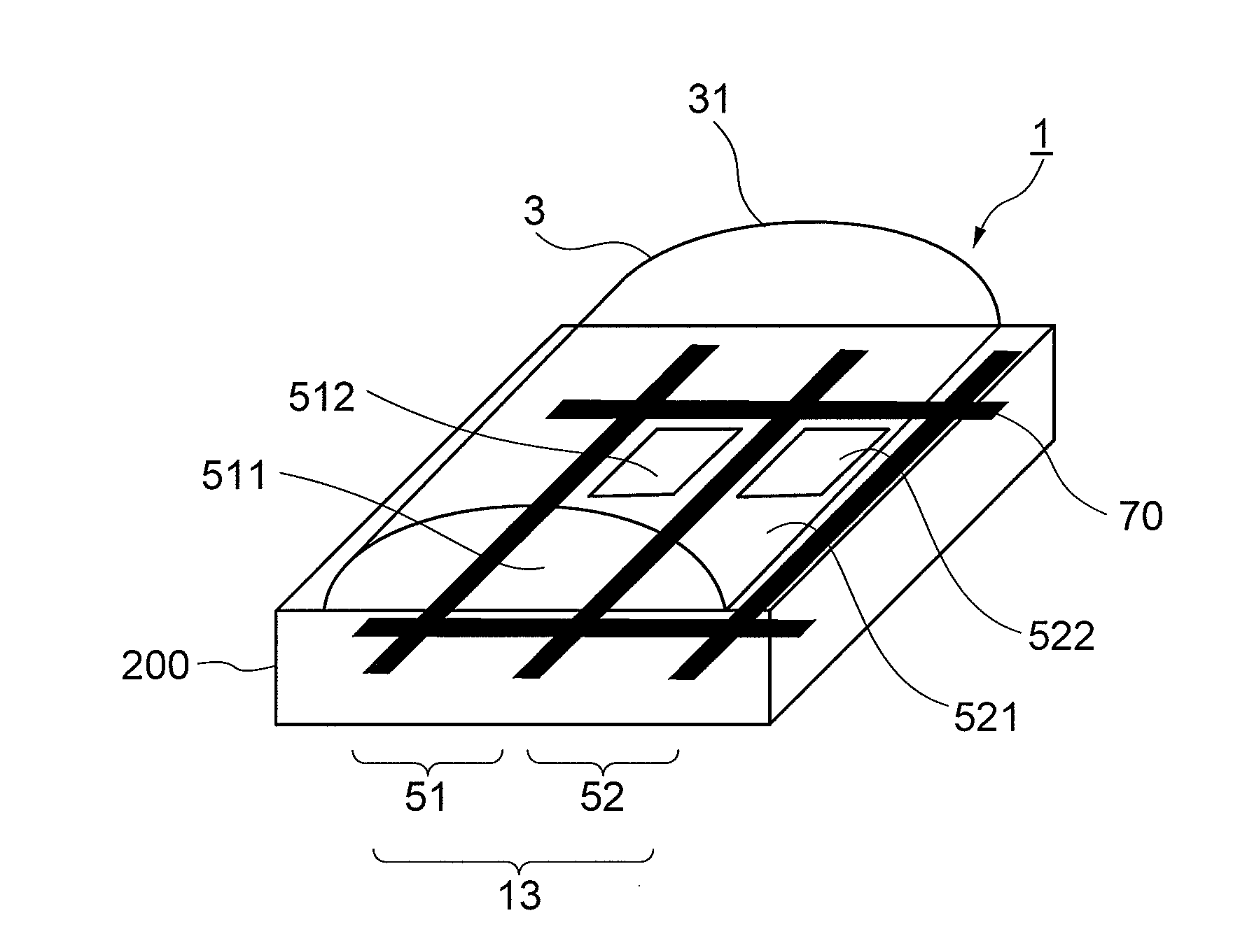
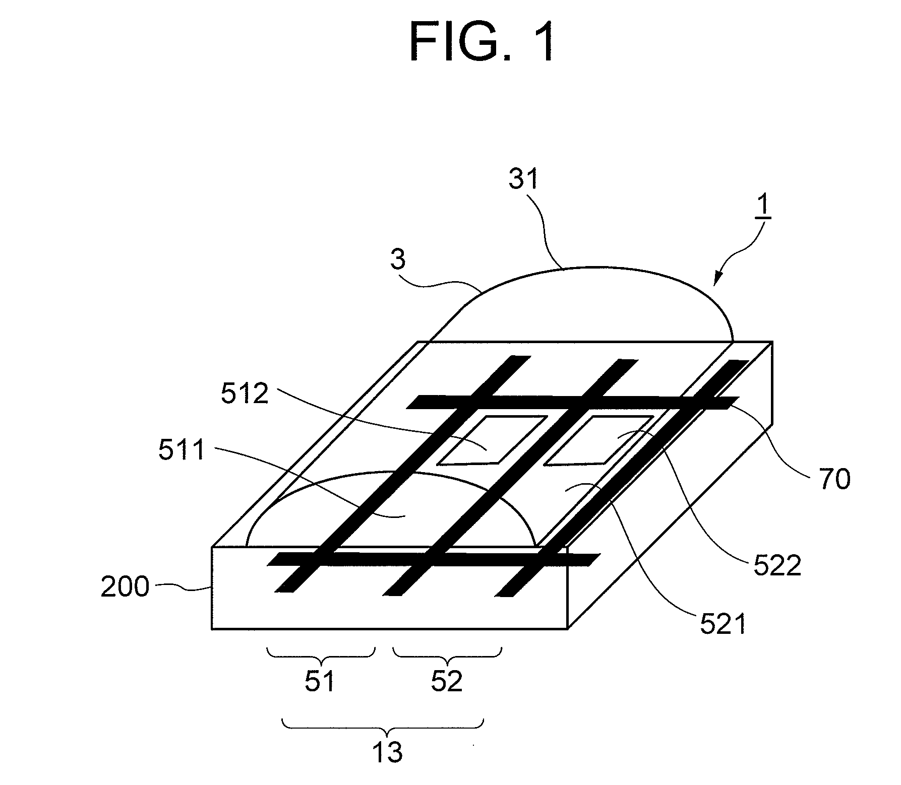
[0127]With the above-described conventional case, when the image distributing device such as the lens is disposed by corresponding to the two pixels (left-eye pixel, right-eye pixel) of the display panel as shown in FIG. 34, there is generated an observing area where the reflective display cannot be recognized visually when the non-reflective display area (transmissive display area) within each of the pixels 51 and 52 is enlarged. This results in deteriorating the visibility of the reflective display. In the meantime, as shown in FIG. 4, regarding the layout of the reflective display areas of the first exemplary embodiment, the reflective display areas of the two display elements neighboring to each other in the direction perpendicular to the image distributing direction 14 are shifted from each other in the +X direction. Thus, it is possible to compensate the reflective display areas that are neighboring to each other in the +Y direction. That i...
second exemplary embodiment
Structure
[0159]Next, a second exemplary embodiment of the invention will be described by referring to FIG. 10-FIG. 12.
[0160]FIG. 10 is a top plan view showing a stereoscopic image display device according to the second exemplary embodiment, and FIG. 11 is a model illustration showing layout of pixel transistors. Further, FIG. 12 is a perspective view showing a fly-eye lens that is used instead of the lenticular lens.
[0161]First, in FIG. 10, the reflective display areas 512 and 522 disposed within the display elements neighboring to each other on the left and right sides are formed with reflection plates that are arranged by being deviated in one or the other with respect to the +Y direction, which are arranged on the top side or the bottom side of the display elements 13 in a scattered manner. The central axis line YL 55 of the left-eye pixel 51, the central axis line YR 56 of the right-eye pixel 52, and the central axis line YG 57 of the display element 13 are glide planes (g) for ...
third exemplary embodiment
[0178]Next, a third exemplary embodiment of the invention will be described by referring to FIG. 13-FIG. 16.
[0179]FIG. 13 is a top plan view showing a part of a stereoscopic image display device according to the third exemplary embodiment. Further, FIG. 14 is a top plan view showing a stereoscopic image display device according to Modification Example 1 of the third exemplary embodiment, FIG. 15 is a top plan view showing a stereoscopic image display device according to Modification Example 2 of the third exemplary embodiment, and FIG. 16 is a top plan view showing a stereoscopic image display device according to Modification Example 3 of the third exemplary embodiment.
(Structure)
[0180]First, the third exemplary embodiment of the invention will be described, and Modification Examples 1-3 will be described thereafter.
[0181]First, as shown in FIG. 13, the reflective display areas 512 and 522 disposed within the display elements 13 neighboring to each other on the left and right sides ...
PUM
 Abstract
Description
Claims
Application Information
 - R&D
- Intellectual Property
- Life Sciences
- Materials
- Tech Scout
- Unparalleled Data Quality
- Higher Quality Content
- 60% Fewer Hallucinations
Browse by: Latest US Patents, China's latest patents, Technical Efficacy Thesaurus, Application Domain, Technology Topic, Popular Technical Reports.
© 2025 PatSnap. All rights reserved.Legal|Privacy policy|Modern Slavery Act Transparency Statement|Sitemap|About US| Contact US: help@patsnap.com


